Assembly – Weed Eater 530088156 User Manual
Page 3
3
S
Move at least 10 feet (3 meters) away from
fueling site before starting engine.
S
Stop engine and allow to cool before remov-
ing fuel cap.
S
Always store gasoline in a container ap-
proved for flammable liquids.
CUTTING SAFETY
WARNING:
Inspect the area before
each use. Remove objects (rocks, broken
glass, nails, wire, etc.) which can be thrown
by or become entangled in line. Hard objects
can damage trimmer head and be thrown
causing serious injury.
S
Use unit properly. Use only for trimming,
mowing, and sweeping. Do not use for edg-
ing, pruning, or hedge trimming. Do not force
unit. It will do the job better, and with less risk
of injury, at the rate for which it was designed.
S
Keep firm footing and balance. Do not over-
reach.
S
Keep all parts of your body away from spin-
ning line and muffler. Keep engine and cutting
head below waist level. A hot muffler can
cause serious burns.
S
Cut only from your right to your left. Cutting
with the line on right side of the shield will
throw debris away from the operator.
S
Use only in daylight or in good artificial light.
S
Use only for jobs explained in this manual.
TRANSPORTING AND STORAGE
S
Stop the unit when not in use.
S
Carry or transport the unit with engine
stopped.
S
Allow the engine to cool; secure unit before
storing or transporting in vehicle.
S
Empty the fuel tank before storing or trans-
porting the unit. Use up fuel left in the car-
buretor by starting the engine and letting it
run until it stops.
S
Store unit and fuel in an area where fuel va-
pors cannot reach sparks or open flames
from water heaters, electric motors or
switches, furnaces, etc.
S
Store the unit out of the reach of children
SPECIAL NOTICE:
This unit is not
equipped with a temperature limiting muffler
and spark arresting screen which meets the
requirements of California Codes 4442 and
4443. All U.S. forest land and the states of
California, Idaho, Maine, Minnesota, New
Jersey, Oregon, and Washington require by
law that many internal combustion engines to
be equipped with a spark arrestor screen. If
you operate in a locale where such regula-
tions exist, you are legally responsible for
installing and maintaining the operating con-
dition of these parts. Failure to do so is a viola-
tion of the law. If a spark arrestor is required
in your area, contact your authorized service
dealer for the proper kit.
SAFETY NOTICE:
Exposure to vibrations
through prolonged use of gasoline powered
hand tools could cause blood vessel or nerve
damage in the fingers, hands, and joints of
people prone to circulation disorders or ab-
normal swellings.
Prolonged use in cold
weather has been linked to blood vessel dam-
age in otherwise healthy people. If symptoms
occur such as numbness, pain, loss of
strength, change in skin color or texture, or
loss of feeling in the fingers, hands, or joints,
discontinue the use of this tool and seek med-
ical attention. An anti-vibration system does
not guarantee the avoidance of these prob-
lems. Users who operate power tools on a
continual and regular basis must monitor
closely their physical condition and the condi-
tion of this tool.
ASSEMBLY
WARNING:
If received assembled,
repeat all steps to ensure your unit is properly
assembled and all fasteners are secure.
Examine parts for damage. Do not use dam-
aged parts.
NOTE:
If you need assistance or find parts
missing or damaged, call 1-800-554-6723.
It is normal for the fuel filter to rattle in the
empty fuel tank.
Finding fuel or oil residue on muffler is normal
due to carburetor adjustments and testing
done by the manufacturer.
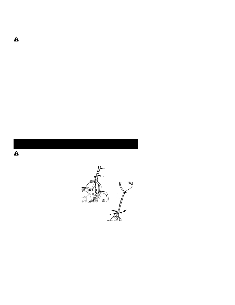
ATTACH THE HANDLE
1. Remove upper wing nut and curved head
tube bolt from upper handle.
2. Loosen lower wing nut on lower handle.
3. Insert upper handle over lower handle.
NOTE:
Ensure upper handle grips are in
position as shown in the following illustrations
(throttle handle grip on left side).
4. Align holes and insert curved head tube
bolt through upper and lower handles.
5. Re--install and securely tighten upper wing
nut onto bolt.
6. Retighten lower wing nut securely.
Upper handle
Upper wing nut
Lower handle
Lower wing nut
Tube bolt