Warning – Weider XP 800 WESY75742 User Manual
Page 15
44
48
Pin
“L”-Slot
15
82
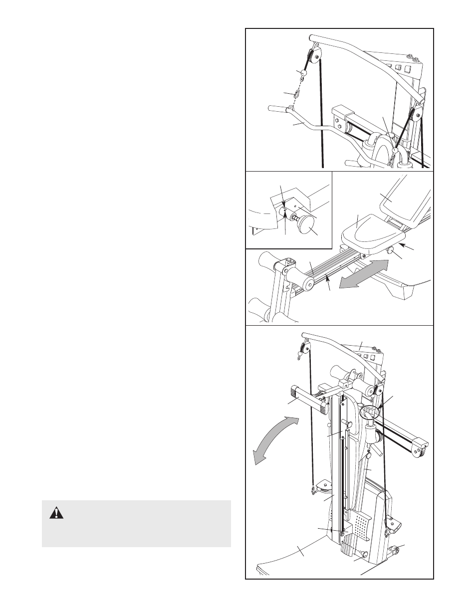
ATTACHING THE ACCESSORIES
To attach the Lat Bar (82) to the high pulleys, first
attach the high pulley to the resistance system (see
ATTACHING THE HIGH PULLEYS on page 13). Then,
attach the Lat Bar to a High Cable (101) with a Cable
Clip (94). Attach the Lat Bar to the other High Cable
in the same manner.
The Handles (not shown) and the Ankle Strap (not
shown) can be attached to the High Cables (101) or
the lower cable (not shown) with Cable Clips (94).
Attach the Hip Strap (not shown) to the ends of the
lower cable with two Cable Clips.
101
94
101
2
4
1
5
37
44
STORING THE RESISTANCE SYSTEM
To store the resistance system, first remove the Leg
Lever (not shown) from the resistance system. Secure
the Seat Carriage (44) at the position closest to the
Leg (5) (see ADJUSTING THE SEAT above). Next,
remove the Storage Knob (29) from the Row Plate
(28). Lift the Leg toward the Top Frame (37), and tight-
en the Storage Knob into the side of the Row Plate
and into the Rail (4).
To move the resistance system, stand behind the
Upright (2) and place the toe of your shoe on the end
of the Base Plate (1) and hold the resistance system
in the indicated area. Tilt the resistance system back
onto the Wheels (65) and roll it to the new location.
WARNING:
Make sure that
Storage Knob (29) is in place and fully tight-
ened each time the resistance system is used.
29
28
65
Hold in
this area
ADJUSTING THE SEAT
The Seat (45) can be secured at various positions on
the Rail (4). To move the Seat, pull the Seat Knob
(48) out as far as it will go and slide the Seat to the
desired position. Engage the Seat Knob into an
adjustment hole in the Rail.
To perform row exercises, the hip strap must be
attached to the mech cable (see ATTACHING THE
ACCESSORIES, above), and the Seat Carriage (44)
must be able to roll along the Rail (4). First, remove
the Backrest (35) from the Seat Carriage (see
ADJUSTING THE BACKREST on page 14). Then,
pull the Seat Knob (48) out as far as it will go, and
turn the Knob so that the pin rests at the end of the
“L”-shaped slot (see the inset drawing).
44
45
35
48
4
Adjustment
Hole