Heating system – White Rodgers 1F80-240 User Manual
Page 3
3
Heating System
1. Move SYSTEM switch to HEAT position. If the heating
system has a standing pilot, be sure to light it.
2. Press
to adjust thermostat setting above room tempera-
ture. The heating system should begin to operate.
3. Press
to adjust temperature setting below room tem-
perature. The heating system should stop operating.
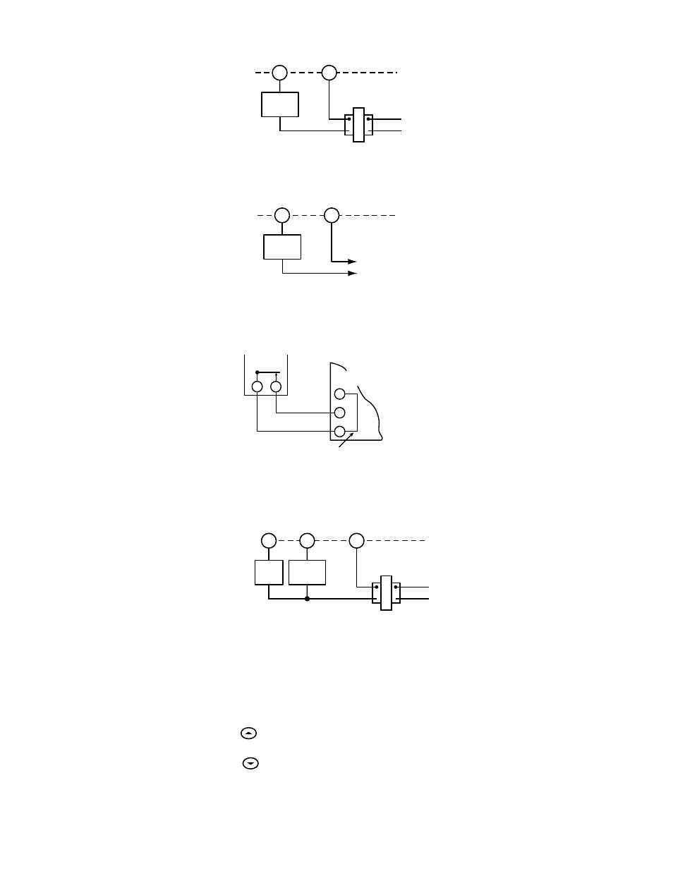
RH
24 VAC
120 VAC
Hot
Neutral
THERMOSTAT
SYSTEM
W
Figure 2. Typical wiring diagram for
heating only, 2-wire, single transformer systems
TRANSFORMER
Heating
System
RH
24 VAC
120 VAC
Hot
Neutral
THERMOSTAT
SYSTEM
G
W
Figure 5. Typical wiring diagram for
heat only, 3-wire, single transformer systems
TRANSFORMER
Heating
System
Fan
Relay
RH
M.V. or 12 V. D.C.
+
-
THERMOSTAT
SYSTEM
W
Figure 3. Typical wiring diagram for
heating only, 2-wire, single transformer systems
TRANSFORMER
Heating
System
3-wire Series 10
Primary Control
(located at furnace)
Thermostat
Add jumper wire
(not provided with thermostat)
R
W
B
R
W
Furnace
Figure 4. Typical wiring diagram for
3-wire SERIES 10 heating systems