Features & operating controls – Wells BWB-1S User Manual
Page 4
2
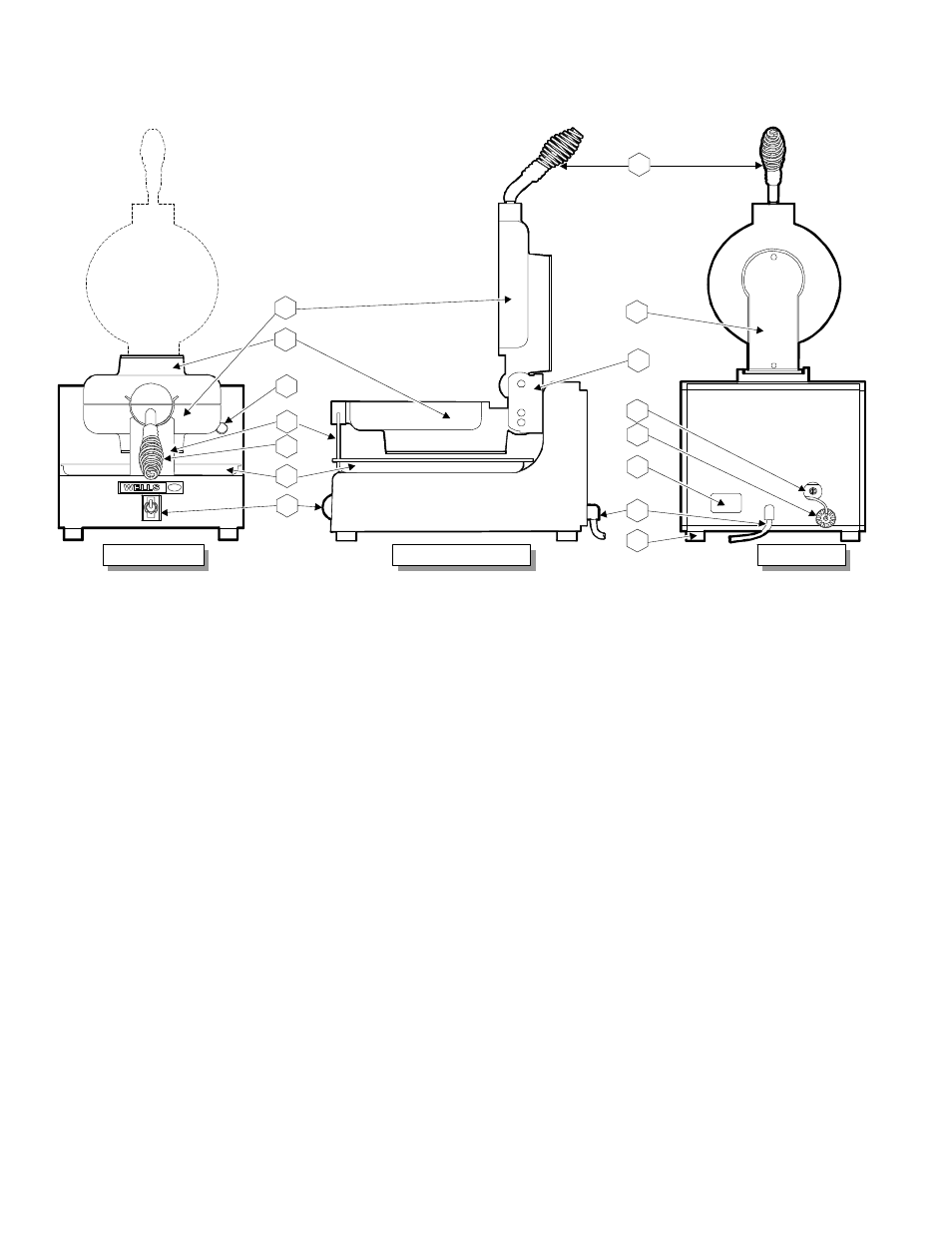
FEATURES & OPERATING CONTROLS
8.
POWER CORD
115VAC. NEMA 5-15P Plug
9.
DATA PLATE
Identifies Manufacturer, Model & Serial numbers;
gives voltage rating.
17.
HANDLE ASSEMBLY
Used to raise/lower top lid and to rotate grids for cooking.
18.
SUPPORT BRACKET
Supports front of grids.
19.
HOLE PLUG ASSEMBLY
Covers and protects timer control.
20.
GRID COVER
Covers and protects electrical wiring in grid.
28.
INDICATOR LIGHT
When lit, indicates timer is in “cook” cycle.
40.
PIVOT ASSEMBLY
Supports back of grids, allows grids to rotate for cooking.
41.
RUBBER FOOT
Non-skid support for baker; allow adjustments for levelling.
42.
LOWER GRID ASSEMBLY
Cooking element (grid); contains temperature control sensor.
43.
UPPER GRID ASSEMBLY
Cooking element (grid).
48.
TIMER
Sounds audible alarm to warn operator at end of bake cycle.
66.
POWER SWITCH
Energizes/de-energizes the baker.
75.
DRIP TRAY
Catches batter drippings for easier clean-up.
.1
1
2
3
4
5
6
66
18
28
42
43
17
8
9
19
48
20
40
41
FRONT VIEW
RIGHT SIDE VIEW
BACK VIEW
shown in “cook” position
shown in “open” position
17
75