Maintenance, Operation, Electrical connections – Wayne WLS200 User Manual
Page 3
If the pump does not operate after
repeated attempts, check the following:
1. Vertical distance of pump to water
level must not be over 25 feet.
2. Suction piping must be air tight.
3. Be sure valve(s) are open if used in
discharge or suction piping.
Never run the
pump with a closed
or clogged discharge. The water inside
the pump could boil and damage the
pump.
Maintenance
Maintain adequate ventilation for the
pump motor. The motor bearings are
permanently lubricated at the factory.
Additional lubrication is not required.
DRAINING FOR WINTER
Always protect pump and piping
against freezing temperatures. If there
is any danger of freezing, drain the
system. To drain the system:
1. Remove the pipe plug from the
discharge tee.
2. Remove the 1/4” plug from the
lower front face of the pump.
3. Drain all piping below the frost line.
3
Operating Instructions and Parts Manual
pump in accordance with the National
Electrical code and all applicable local
electrical codes.
The motor must be grounded by
connecting a copper conductor to the
grounding screw provided within the
wiring compartment.
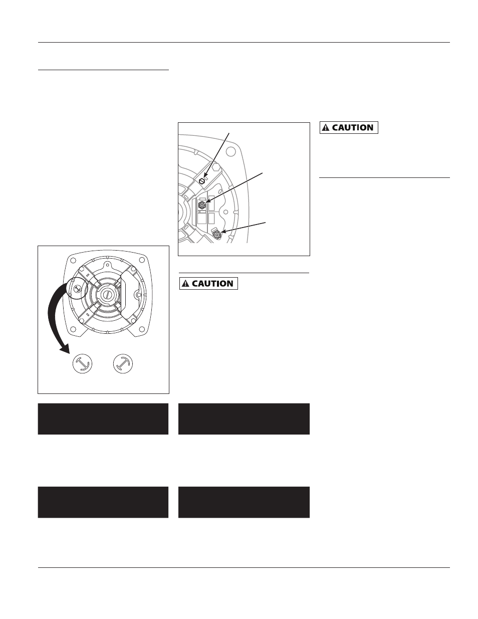
The voltage of power supply must match
the voltage of the pump. The WLS75,
WLS100 and WLS150 have dual voltage
motors preset at the factory to 230 volts.
The motors can be converted to 115 volts
by turning the voltage selector to the
desired voltage (See Figure 5). Use a
needle nose pliers to pull the selector out
approximately 1/4”, rotate and then
reinsert in correct position. The WLS200
cannot be converted; the motor is
230 volts only.
CONNECTING WIRES
Terminal cover must be in place for safe
operation. Ground in accordance with local
and national electrical codes. Keep fingers
and objects away from openings and
rotating parts. Disconnect power sources
before touching internal parts. See figure 6
for appropriate wiring locations.
Operation
Never run the
pump dry. Running
pump without water may cause seal
damage. Fill the pump with water
before starting.
PRIMING THE PUMP
After pump installation is complete, the
pump must be primed. Remove the
pipe plug in the discharge piping and
fill the pump and suction pipe with
clean water. Turn power to pump on. If
the pump does not pump water in 10
minutes, turn off the pump and refill
with clean water.
115 V
230 V
115 V
230 V
Figure 5 - Voltage Selector
Electrical Connections
(Continued)
Lift
in
Feet
3/4 HP Pump Capacity in
GPH Operating Pressure (psi)
10
20
30
5
3900
3320
2320
10
3780
3120
2100
15
3600
2910
1190
20
3250
2670
990
25
3010
2560
840
Lift
in
Feet
1-1/2 HP Pump Capacity in
GPH Operating Pressure (psi)
10
20
30
40
5
4790
4480
3480
2060
10
4610
4310
3190
1520
15
4320
4040
2900
0
20
3900
3720
2680
0
25
3810
3300
2390
0
Lift
in
Feet
2 HP Pump Capacity in GPH
Operating Pressure (psi)
10
20
30
40
5
5980
5560
4310
3060
10
5410
5220
4090
2880
15
5230
4980
3900
2570
20
4120
3840
3510
2210
25
3980
3600
3300
0
Lift
in
Feet
1 HP Pump Capacity in GPH
Operating Pressure (psi)
10
20
30
5
4410
3920
2570
10
4180
3520
2300
15
3830
3340
1780
20
3680
3060
1160
25
3340
2720
1260
www.waynepumps.com
WLS75, WLS100
WLS150, WLS200
Figure 6 - Connecting Wire
Ground Screw
Ungrounded
Line (L1)
Terminal
Board (L2)