Ps/bc installation, Pump installation, Continued) – Wayne 353601-001 User Manual
Page 4
4
Operating Instructions and Parts Manual
3. A check valve will be required in
the discharge line of BOTH the
Main AC pump and the ESP45
pump to prevent recirculation of
water into the sump pit. System will
not function without two check
valves.
4. Cut a 4’ section of 1
1
/
4
" or 1
1
/
2
"
diameter rigid PVC pipe. Cement
1
1
/
2
" pipe to a threaded fitting.
Cement 1
1
/
4
" pipe into pipe
coupling. Attach 1
1
/
4
" pipe section
to the ESP45 discharge adapter.
5. Screw on to pump discharge.
Be careful not to
strip or cross thread
plastic fittings or check valves. Flex hose
is not recommended. Rigid PVC or metal
pipe is required for a permanent
installation.
6. Place the pump with the 4’ section
of PVC pipe on the sump floor or
on an elevated surface if required.
7. Attach a rubber check valve (sold
separately) to the top of the
discharge pipe. This will allow the
pump or check valve to be removed
easily for servicing.
8. Duplicate the discharge piping
arrangement for the primary AC
pump if the existing discharge line
has to be adjusted to accommodate
a second pump.
9. Glue a 45º elbow to the short pipe
on the ESP45 pump. Glue a “Y”
adapter to the short pipe on the
existing pump, as shown in
illustration for Method 2.
10. Glue a short piece of PVC pipe
between the 45º elbow and the “Y”.
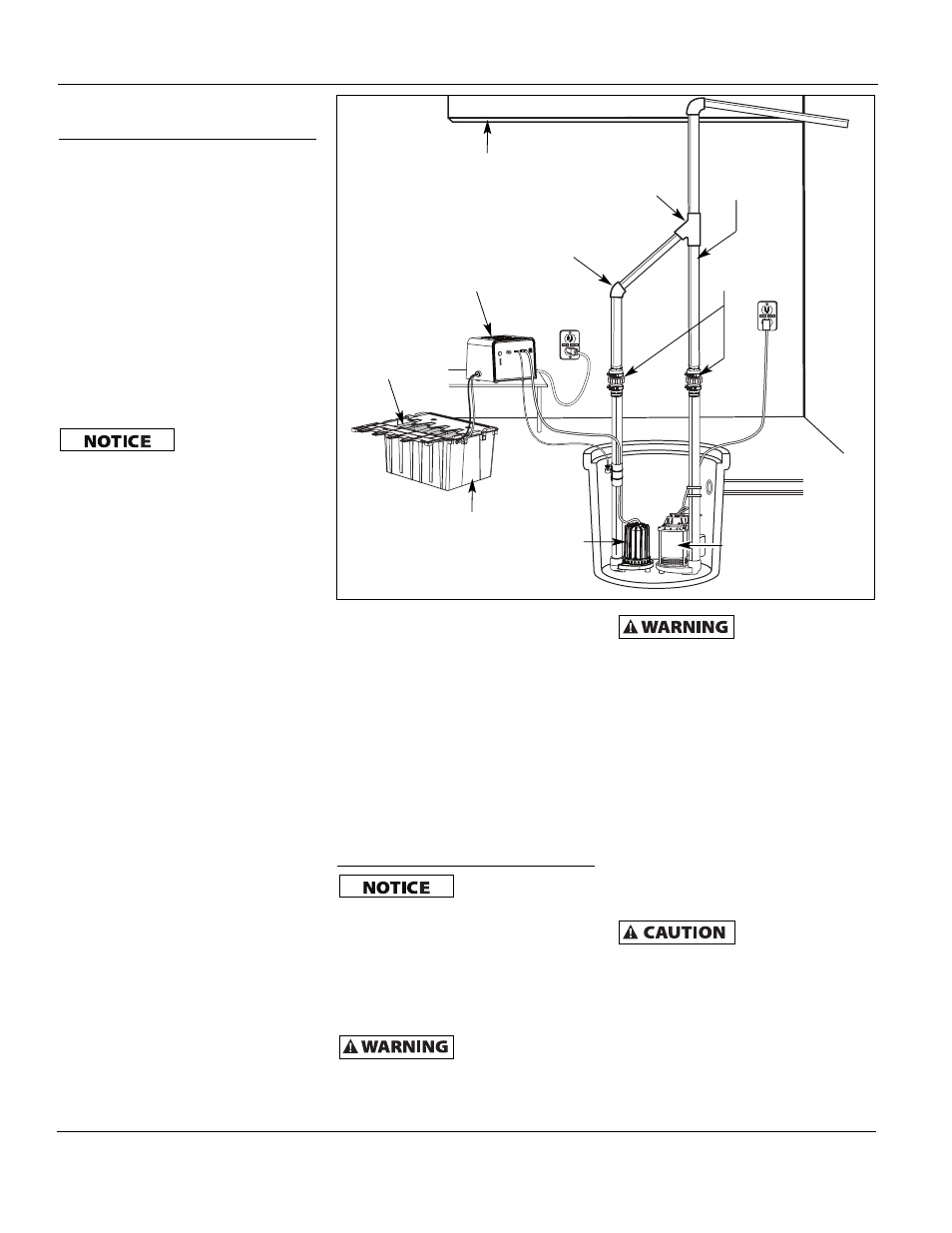
NOTE: Check valves can be placed
directly in the pump discharge if
desired. However, for ease of
disassembly, it is recommended that
check valves be placed above the sump
as shown in Figure 3.
The remainder of the discharge pipe
installation will vary depending on
individual circumstances. Using sound
plumbing practices, route the
discharge pipe to an exterior wall by
the shortest distance.
Methods 1 and 2
Install float switch at least 10”-12”
above bottom of sump pit so that
backup unit turns on only when the
water level is higher than the normal
“on” level for main pump. Use the hose
clamps provided to secure the switch to
the discharge pipe. Make sure power
wires and hose clamp ends do not
interfere with float switch, pump inlet,
or main pump operation. Backup pump
must not be allowed to run dry.
PS/BC Installation
Use Power Supply/
Battery Charger
(PS/BC) indoors, in a well-ventilated
area. Do not expose PS/BC to rain or
snow. Do not use an extension cord. Do
not disassemble PS/BC. Be sure PS/BC
ventilation holes are unobstructed. If
PS/BC is dropped or damaged, do not
operate; return to manufacturer for
service.
Risk of electrical
shock! Use a GFCI
(Ground Fault Circuit Interrupter)
receptacle to reduce the risk of fatal
electrical shock. Grounded receptacle must
be rated for at least 5 amps.
Always disconnect
AC power and
remove pump fuse before connecting or
disconnecting battery.
1. Select a suitable position on the floor
near the sump pit to place the battery
case. Be certain that the PS/BC power
cord will reach AC power, and that
the sump pump power cord will reach
the PS/BC. Make sure the battery case
vent holes are unobstructed.
ELEVATE PS/BC BY MOUNTING ON
WALL OR SETTING ON A SHELF. SLOTS
IN THE BACK SIDE OF PS/BC ARE
AVAILABLE FOR WALL MOUNTING.
Control Box Installation
If cables are
reversed, damage
to the PS/BC or battery could result,
and warranty will be void.
Dangerous hydrogen gas can be
released from batteries while charging.
Sparks can ignite the gas in an
enclosed space. Wear safety goggles
when connecting batteries. Battery
connections should be made in a well-
ventilated area.
www.waynepumps.com
Pump Installation
(Continued)
Figure 3 - Method 2
Floor
Joist
“Y”
Connector
45°
Elbow
Rigid PVC
Pipe
Check Valve
(See Step 10)
PS/BC
ESP45
Pump
Existing Pump
Batteries
Battery
Box