1 operator’s area, 2 control panel & steering control levers – Wright 54700 and higher User Manual
Page 14
13
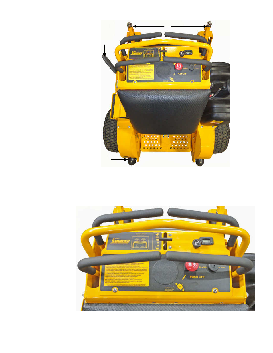
3.1 Operator’s Area
1.
Anti-Tip Wheels
2. Brake Handle
3. Caster Arms/Yokes
4. Dash Panel
5. Fuel Tank
6. Upright Pad
7. Spring Loaded Foot Platform
3.2 Control Panel & Steering Control Levers
The Stander speed and direction are controlled by using the control handles. Moving the control handles
equal distance forward or backward the machine moves in a straight line. By releasing the control handles
during operation, the controls will return to the neutral position and the machine will stop.
1. Control Levers
2. Stationary Handle Bar
3. Throttle
4. Choke
5. Digital Hour Meter
6. PTO Switch
7. Ignition Switch
4
2
1
3
5
6
7
2
1
1
1
1
5
4
3
6
7