Weed Eater 530163734 User Manual
Page 10
10
If the unit
still
doesn’t
start,
refer to
TROUBLESHOOTING
TABLE
or
call
1-800-554-6723.
OPERATING THE COUPLER
This model is equipped with a coupler which
enables optional attachments to be installed.
The optional attachments are:
MODEL:
Edger
1000E
. . . . . . . . . . . . . . . . . . . . . . .
Cultivator
2000T
. . . . . . . . . . . . . . . . . . . .
Blower
3000B
. . . . . . . . . . . . . . . . . . . . . .
Brushcutter
4000C
. . . . . . . . . . . . . . . . . .
WARNING:
Always stop unit and dis-
connect spark plug before removing or instal-
ling attachments.
REMOVING TRIMMER ATTACH-
MENT (OR OTHER OPTIONAL AT-
TACHMENTS)
CAUTION:
When removing or installing at-
tachments, place the unit on a flat surface for
stability.
1.
Loosen the coupler by turning the knob
counterclockwise.
Coupler
Knob
LOOSEN
TIGHTEN
Upper Tube
Lower
Attachment
2.
Press and hold the locking/release button.
Locking/Release
Button
Coupler
Upper Tube
Lower Attachment
3.
While securely holding the engine and
upper tube, pull the attachment straight
out of the coupler.
INSTALLING OPTIONAL ATTACH-
MENTS
1.
Remove the tube cap from the attach-
ment (if present).
2.
Position locking/release button of attach-
ment into guide recess of coupler.
3.
Push the attachment into the coupler until
the locking/release button snaps into the
primary hole.
4.
Before using the unit, tighten the knob se-
curely by turning clockwise.
Coupler Primary Hole
Upper
Tube
Locking/
Release
Button
Attachment
Guide Recess
WARNING:
Make sure the locking/
release button is locked in the primary hole
and the knob is securely tightened before op-
erating the unit.
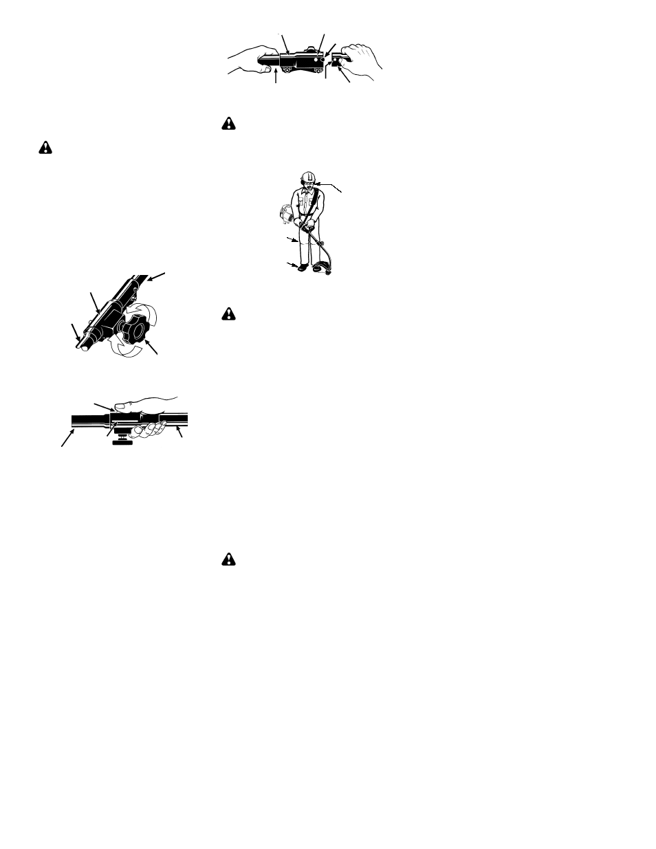
OPERATING POSITION
Eye Protection
Long Pants
Heavy Shoes
ALWAYS WEAR:
Cut from your right to your left.
WARNING:
Always wear eye protec-
tion. Never lean over the trimmer head.
Rocks or debris can ricochet or be thrown into
eyes and face and cause blindness or other
serious injury.
Do not run the engine at a higher speed than
necessary. The cutting line will cut efficiently
when the engine is run at less than full throttle.
At lower speeds, there is less engine noise
and vibration. The cutting line will last longer
and will be less likely to “weld” onto the spool.
Always release the throttle trigger and allow
the engine to return to idle speed when not
cutting.
To stop engine:
S
Release the throttle trigger.
S
Move the ON/OFF switch to the OFF posi-
tion.
TRIMMER LINE ADVANCE
The cutting head advances line automati-
cally. Do not tap head on the ground to ad-
vance line. This may break parts and cause
cutting head to malfunction.
Upon unit start up, the line will advance auto-
matically to the correct cutting path length.
Always keep the shield in place when the tool
is being operated.
WARNING:
Use only .080” (2 mm)
diameter round line. Other sizes and
shapes of line will not advance properly and
will result in improper cutting head function or