Operation, Configuration menu, The thermostat buttons and switches (see fig. 8) – White Rodgers 1F86-344 User Manual
Page 4: The display
4
CONFIGURATION MENU
The configuration menu allows you to set certain thermostat
operating characteristics to your system or personal require-
ments.
Move SYSTEM switch to the OFF position, then press
and
at the same time to enter the configuration menu. The
display will show the first item in the configuration menu.
The configuration menu chart below summarizes the configura-
tion options. An explanation of each option follows.
Press
and
to change to the next menu item. To exit the
menu, move the SYSTEM switch to HEAT or COOL. If no keys
are pressed within fifteen minutes, the thermostat will exit the
configuration menu.
1
Step
Press Button(s)
Displayed (Factory Default)
Press or to select:
COMMENTS
Set SYSTEM
switch to OFF
Set SYSTEM
switch to HEAT
or COOL
2
(FA)
SL
SYSTEM switch must be OFF to configure thermostat options
8
LOC
(OFF)
ON
0 HI
(0)
4 LO to
4 HI
(
°
F)
°
C
Returns to normal operation
Select Compressor lockout OFF or ON
Select temperature display adjustment higher or lower
Select temperature display to
°
F or
°
C
and
3
d-L
(ON)
OFF
Select display backlight OFF or ON
Select FA or SL (Fast or Slow) heating cycle rate
Configuration Menu
* Press and
to advance to next item
and
and
and
and
4
5
6
7
FILTER
(000)
0 to 1950 hours
(in 50 hour increments)
Select Filter replacement run time
and
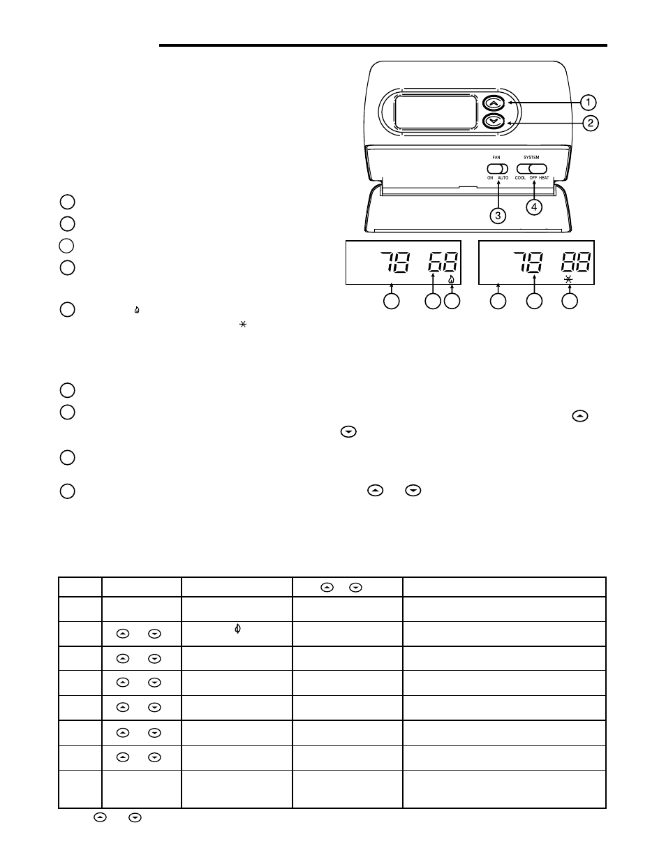
Before you begin using your thermostat, you should be familiar
with its features and with the display and the location and
operation of the thermostat buttons. Your thermostat consists of
two parts: the thermostat cover and the base. To remove the
cover, pull it straight out from the base. To replace the cover, line
up the cover with the base and press until the cover snaps onto
the base.
The Thermostat Buttons and Switches
(see fig. 8)
1 Raises temperature setting.
2 Lowers temperature setting.
3
FAN switch (ON, AUTO).
4 SYSTEM switch (COOL, OFF, HEAT).
The Display
5 Flame icon ( ) is displayed when the SYSTEM switch is in
the HEAT position. Snowflake icon ( )is displayed (non-
flashing) when the SYSTEM switch is in the COOL posi-
tion. Snowflake is displayed (flashing) if the thermostat is
in lockout mode to prevent the compressor from cycling
too quickly.
6 Displays current temperature.
7 Displays "FILTER" when the system has run for the se-
lected filter time period as a reminder to change or clean
your air filter.
8 Displays set point temperature (this is blank when SYS-
TEM switch is in the OFF position).
9 Displays "BATTERY" and "LO" in the current tempera-
ture location when the 2 "AA" batteries are low and should
be replaced.
5
8
7
9
5
6
Figure 8. Thermostat display, buttons, and switches
F
C
BATTERY
FILTER
OPERATION