Assembly, Warning – Weed Eater 245157 User Manual
Page 4
4
ASSEMBLY
WARNING:
If received assembled,
review all assembly steps to ensure your unit
is properly assembled and all fasteners are
secure.
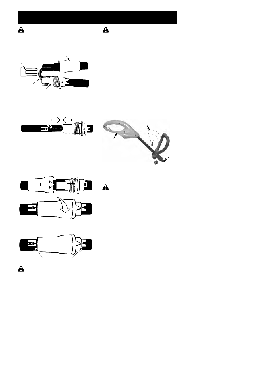
TUBE ASSEMBLY
Wire protector
Upper Locking Sleeve Assembly
Lower Locking Sleeve Assembly
2. Align upper tube groove with triangle on
lower locking sleeve assembly. Push
tubes together until they snap into place.
Alignment Triangle
Upper Tube
Groove
3. Try to pull tubes back apart. If the tubes do
not come apart, they are properly snapped
into place. If the tubes come apart, repeat
step 1 and push until the tubes snap into
place.
4. Slide upper locking sleeve assembly over
lower locking sleeve assembly and tight-
en by turning clockwise.
5. Ensure locking sleeve assembly and
alignment decals appear as illustrated be-
low.
Alignment decals
WARNING:
Failure to completely en-
close excess wires in upper tube during assem-
bly of the unit may result in damage to the wires
and/or the unit or serious injury to the operator
including electrocution.
WARNING:
The upper and lower
tubes must be snapped together, remain per-
manently assembled together and the locking
sleeve assembly must be fully tightened be-
fore and during use to avoid serious injury to
the operator and/or damage to the unit. DO
NOT attempt to disassemble unit after initial
assembly.
INSTALLATION OF ASSIST HANDLE
1. Place unit on a flat surface.
2. Remove knob and bolt from kit.
3. Firmly push the assist handle over the
tube. To make installation easier, tilt han-
dle toward trigger housing while pushing
down (see illustration).
4. Install bolt in handle. Thread knob
onto bolt.
5. Adjust the handle up or down the tube to a
comfortable postion; tighten knob secure-
ly.
ATTACHING EDGE GUIDE AND
SHIELD
WARNING:
The shield must be prop-
erly installed. The shield provides partial
protection from the risk of thrown objects to
the operator and others. Your unit is equipped
with a line limiter blade, which cuts excess
line to the proper length while running. The
line limiter blade (on underside of shield) is
sharp and can cut you.
NOTE:
If shield is not properly installed, dam-
age to unit (including motor failure) will result.
1. Insert edge guide into two holes in shield.
NOTE:
Edge guide
must be positioned on
shield prior to installation on motor housing
(see following illustration).
Assist handle
Tube
Trigger
housing
Wires
1. Remove the wire protector from the
tubes and discard.