Selecting the voltage for your spa, Wiring instructions, Electrical installation – Watkins C45S User Manual
Page 8: 230 volt permanently connected, Electrical requirements and precautions
SELECTING THE VOLTAGE FOR YOUR SPA
These spas are designed to operate at 230 volts, 60 Hz. When these spas are connected to 230 volts, the heater will provide approximately 4000 watts of heat when the
pump is operating in LOW or HIGH speed and the thermostat is calling for heat. All electrical connections must be made in accordance with the wiring information
contained in the electrical control box or on the back of the field wiring access panel of the equipment module.
230 VOLT PERMANENTLY CONNECTED
When using 230 volt power supply, installation of a 50 amp dedicated circuit is required. Your spa must be hardwired direct to a GFCI-protected subpanel by a licensed
electrician. A wiring diagram is provided inside the equipment module showing where the connections are to be made.
ELECTRICAL REQUIREMENTS AND PRECAUTIONS
Your spa has been carefully designed to give you maximum safety against electrical shock. Connecting the spa to an improperly wired circuit will negate many of the
spa’s safety features. Improper wiring may also cause electrocution, risk of fire, and other risks of injuries. Please read and follow the electrical installation requirements
and instructions for your spa completely!
WIRING INSTRUCTIONS
NOTE: The subpanel must be placed within 100 feet of the main electrical service panel, and between 5 and 50 feet away from the spa. All electrical connections must
be made in accordance with the wiring information contained in this manual and on the back of the field wiring access panel of the control box.
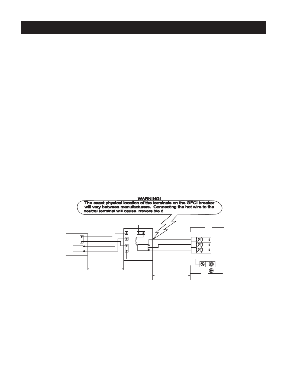
Refer to the wiring diagram below.
1. Connect the #8 AWG, WHITE [NEUTRAL] wire from the Neutral/Ground Bar on the main electrical service to the WHITE [NEUTRAL, Panel Neutral, Pigtail] of the
subpanel.
2. Connect the #8 AWG, BLACK [L1] wire from the main electrical service to the subpanel [terminal L1].
3. Connect the #8 AWG, RED [L2] wire from the main electrical service to the subpanel [terminal L2].
4. Connect the #8 AWG, GREEN wire from the Neutral/Ground Bar on the main electrical service to the subpanel GRD.
5. Connect the #8 AWG, WHITE [NEUTRAL] wire from the subpanel to the Neutral terminal on the spa’s control box.
6. Connect the #8 AWG, BLACK [L1] wire from the subpanel breaker to terminal [L1] on the spa’s control box.
7. Connect the #8 AWG, RED [L2] wire from the subpanel breaker to terminal [L2] on the spa’s control box.
8. Connect the #8 AWG,GREEN wire from the subpanel GRD to the GROUND terminal of the spa’s control box.
9. Bond the spa to all exposed metal equipment or fixtures, handrails, and concrete pad pre N.E.C. and all local codes.
ELECTRICAL INSTALLATION
5
CONTROL BOX
CONTROL BOX
PANEL
PANEL
ELECTRICAL
ELECTRICAL
MAIN SERVICE
MAIN SERVICE
LESS THAN 100 FT.
LESS THAN 100 FT.
#8 AWG RED, L2
#8 AWG RED, L2
#8 AWG BLACK, L1
#8 AWG BLACK, L1
#8 AWG GREEN, GROUND
#8 AWG GREEN, GROUND
#8 AWG WHITE, NEUTRAL
#8 AWG WHITE, NEUTRAL
50A
50A
WITHIN SIGHT OF THE SPA
WITHIN SIGHT OF THE SPA
THE SUB-PANEL MUST BE
THE SUB-PANEL MUST BE
MORE THAN 5 FEET
MORE THAN 5 FEET
DO NOT EXCEED 50 FEET
DO NOT EXCEED 50 FEET
WITH GFCI
WITH GFCI
BREAKERS
BREAKERS
50A
50A
SUB-PANEL
SUB-PANEL
L2
L2
GRD
GRD
L2, HOT, #8 AWG RED
L2, HOT, #8 AWG RED
L1, HOT, #8 AWG BLACK
L1, HOT, #8 AWG BLACK
GROUND, #8 AWG GREEN*
GROUND, #8 AWG GREEN*
N, NEUTRAL, #8 AWG WHITE
N, NEUTRAL, #8 AWG WHITE
L1L
1
L2L
2
N
PERMANENTLY CONNECTED
PERMANENTLY CONNECTED
230 VAC, 50A, 60Hz, MODELS
230 VAC, 50A, 60Hz, MODELS
230VAC, 50 Amp
230VAC, 50 Amp
2-POLE
2-POLE
CIRCUIT BREAKER
CIRCUIT BREAKER
(NON GFCI)
(NON GFCI)
N
L1
L1
GNDG
N
D
JUMPERS REQUIRED
JUMPERS REQUIRED
NO POWER
NO POWER