Installation, Placement, Ceiling mount – White Rodgers CSC1000 User Manual
Page 3
3
3/8 " DIA. STEEL
THREADED ROD
COVER
WELD NUT
2X4
ROOF SUPPORT JOIST
NUT & WASHER TOP AND BOTTOM
ALTERNATE 2X4
MOUNTING METHOD
FALSE
CEILINGS
WELD NUTS
HANG THE AIR CLEANER
FROM THE TREADED STEEL
RODS TO TOP PLATE
**ALTERNATIVE: Wood 2 x 4's can be used at the
False Ceiling Level and supported from above with
16 ga. wire min.
INSTALLATION
PLACEMENT
The installer must be qualified to make approved electrical
connections and a safe ceiling installation with attention to the
best placement as shown in the following drawings.
The electronic air cleaner should be mounted on the ceiling near
the center of the room. Air is drawn through the bottom of the air
cleaner and discharged in four directions. Divide larger rooms
into sections and use a unit in each section (see Fig. 2).
CEILING MOUNT
The air cleaner is mounted to the ceiling. The mounting holes in
the unit are spaced 16” and 26
1
/
2
” between centers (Fig. 3).
Mounting Detail
Be sure to select the mounting location so that the structure
above is sufficiently strong to support the unit (approximately 70
lbs). See Fig.4.
CAUTION: Do not allow the unit to be supported by the
ceiling tile grid suspension.
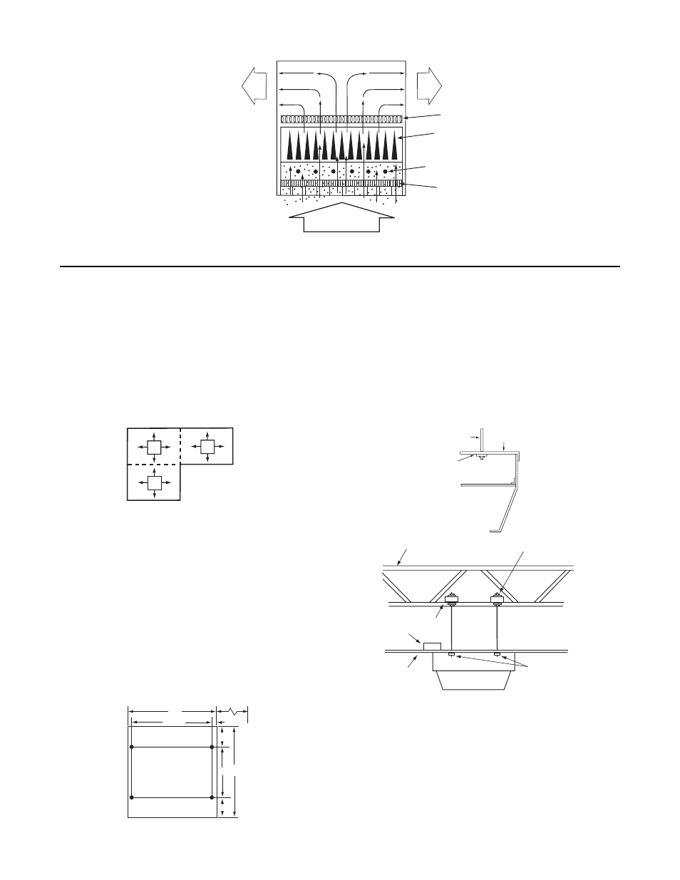
FIG. 1 Illustration of Air Cleaning Process
Charcoal Filter
Reduces Odors
DIRTY
AIR IN
Collecting Plates attract
and hold dirt particles
like a magnet
Ionizing wires give dirt
particles a positive charge
Prefilter Screen
Clean
Air Out
Clean
Air Out
Check existing air circulation in the room. The air cleaner should
be installed so that it aids the circulation already established.
When air flow patterns are not immediately apparent, observe
the smoke from a cigarette in various locations within the room.
Do not locate the air cleaner near a heating or air conditioning
intake or exhaust vent if it interferes with the air flow discharge
and return air to the heating or air conditioning unit.
FIG. 2 Divide large room into areas
FIG. 3 Installation Dimensions in Inches
FIG. 4 Mounting details
28
26 1/2
16 28
6
6
3/4
TOP
FRONT
ALLOW AT LEAST 14" (356 mm)
FOR CELL REMOVAL