Specifications, Caution ! warning, Installation – White Rodgers 50M56U-843 User Manual
Page 2
2
SPECIFICATIONS
MOUNTING AND WIRING
All wiring should be installed by a qualified heating and air
conditioning contractor or licensed electrician, according to
local and national electrical codes and ordinances.
The control must be secured to an area that will experience a
minimum of vibration and remain below the maximum ambient
temperature rating of 176°F. The control is approved for
minimum ambient temperatures of -40°F.
When mounting the control, any orientation is acceptable.
Choose a location that will not damage, obstruct or place
stress on the control’s terminations, system wiring harness or
system components. After finding a suitable location, drill four
(4) 1/8” holes for mounting control. To ensure proper mounting
hole locations, use the control as a template. When drilling
the holes, take care so that the transformer, wiring harness or
other system components are not damaged. Four (4) #8 sheet
metal screws are provided to complete the installation.
Refer to the wiring diagram and wiring table when connecting
the 50M56U-843 control to other components of the system.
UL approved, 105°C rated 18 gauge, stranded, 2/64” thick
insulation wire is recommended for all low voltage safety circuit
connections.
UL approved 105°C rated 16 gauge min., stranded, 4/64”
thick insulation wire is recommended for all line voltage
connections.
After installation or replacement, follow appliance manufacturer’s
recommended installation or service instructions to ensure
proper operation.
ELECTRICAL RATINGS [@ 77°F (25°C)]:
Input Voltage: 25 VAC 50/60 Hz
Max. Input Current @ 25 VAC: 0.45 amp
Relay Load Ratings:
Valve Relay: 1.5 amp @ 25 VAC 50/60 Hz 0.6 pf
Ignitor Relay: 6.0 amp @ 120 VAC 50/60 Hz (resistive)
Inducer Relay: 2.2 FLA–3.5 LRA @ 120 VAC
Circulator Relay: 14.5 FLA–25.0 LRA @ 120 VAC
Flame Current Requirements:
Minimum current to insure flame detection: 1 µa DC*
Maximum current for non-detection: 0.1 µa DC*
Maximum allowable leakage resistance: 100 M ohms
*Measured with a DC microammeter in the flame probe lead
OPERATING TEMPERATURE RANGE:
-40° to 176°F (-40° to 80°C)
HUMIDITY RANGE:
MOUNTING:
Surface mount multipoise
Timing Specs: (@ 60 Hz)
maximum
Flame Establishing Time:
0.8 sec
Flame Failure Response Time:
2.0 sec
Gases Approved: Natural, Manufactured, Mixed, Liquified
Petroleum, and LP Gas Air Mixtures are all approved for use.
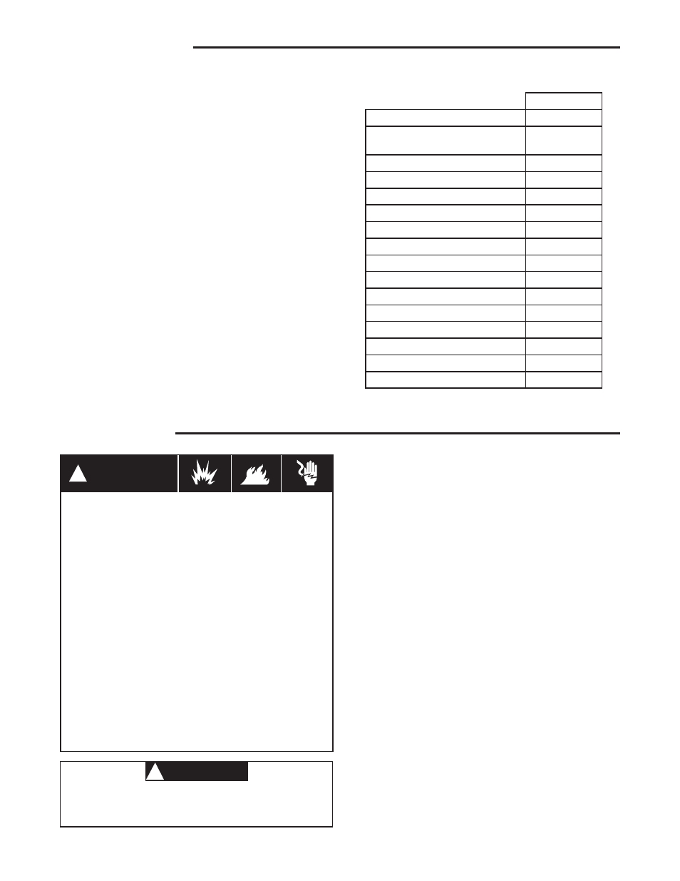
TIMING SPECIFICATIONS
(All times are in seconds, unless noted otherwise
50M56U-843
Pre-Purge
30
Initial Ignitor Warm-Up
(1st 64 attempts)
17
Maximum Ignitor Warm-Up
19
Ignition Activation Period
2
Trial for Ignition Period
4
Retries
2
Recycles
3
Valve Sequence Period
12
Interpurge
60
Post-Purge
25
Lockout Time
275
Heat Delay-To-Fan-On
30
Heat Delay-To-Fan-Off
100/150*
Cool Delay-To-Fan-On
6
Cool Delay-To-Fan-Off
45
Auto Reset
60 minutes
*These times will vary depending on option switch
position. See OPERATION section for further infor-
mation.
Do not short out terminals on gas valve or primary
control. Short or incorrect wiring may damage the
thermostat.
CAUTION
!
WARNING
!
FIRE HAZARD
• Do not exceed the specified voltage.
• Replace existing control with exact model and
dash number.
• Protect the control from direct contact with water
(dripping, spraying, rain, etc.).
• If the control has been in direct contact with
water, replace the control.
• Label all wires before disconnection when serv-
icing controls. Wiring errors can cause improper
and dangerous operation.
• Route and secure wiring away from flame.
SHOCK HAZARD
• Disconnect electric power before servicing.
• Ensure proper earth grounding of appliance.
• Ensure proper connection of line neutral and line
hot wires.
EXPLOSION HAZARD
• Shut off main gas to appliance until installation
is complete.
INSTALLATION