Vermont Castings TP-250 User Manual
Page 3
3
19. Using a 7/16” nut driver, remove the threaded plug
from the test port.
20. Thread the supplied extension adaptor into the
open test port.
21. Attach a 1/4” diameter pressure gauge flexible hose
fully onto the barb of the adaptor.
22. Turn on gas supply and operate valve with remote
control as needed to indicate gas pressure. The
manifold pressure for LP should be approximately
10.0” wcp.
CAUTION: Turn off the valve and gas supply
before removing test port adaptor and replac-
ing plug.
23. After test, remove adaptor and replace plug.
24. Turn on gas supply and check that plugs are tight
and leak free.
25. Follow instructions in Homeowner’s Manual to
re-assemble brick panels, logs, lava rock, volcanic
rock, embers and andirons.
26. Replace glass frame.
27. Conversion complete.
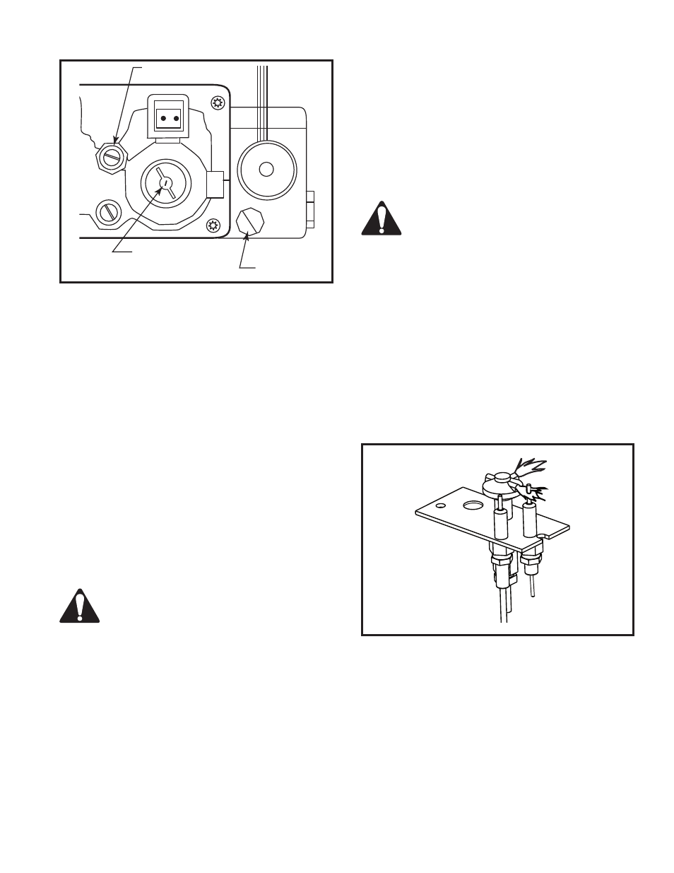
Pilot Flame Adjustment
Typically, the top 3/8” or 1/2” of the thermopile should
be engulfed in the pilot flame. (Fig. 8)
To adjust pilot burner: Adjust pilot screw on valve to
provide properly sized flame..
13. Reinstall burner to original position. Reinstall burner
leg, burner tube and fettle. Re-attach supply tube to
gas supply fitting. Using a back-up wrench, tighten
securely.
14. Test for leaks. Apply electric and gas to the system.
15. Light the pilot burner using the remote control. With
soapy solution check for leaks around the pilot as-
sembly where the tube enters the pilot assembly.
Tighten fitting if necessary.
16. Light the main burner and check for leaks around
the burner supply tube fittings and burner orifices.
Tighten if necessary.
17. Turn fireplace OFF.
18. After the conversion and leak checks have been
made, manifold outlet pressure can be checked
with a manometer at the test ports located at the
side front edge of the fireplace opening. The lower
test port is manifold outlet pressure.
CAUTION: Turn off the gas supply before
removing test port plug.
�����
�����������������������
����
�
��
�
��
��
��
Minimum Rate
Screw
CO137
Fig. 7 Remove black plastic cap and adjust rotary knob to
correct gas type. (LP position shown) Replace minimum rate
screw with one supplied in conversion kit.
Gas Type
Marker
Pilot Adjustment Screw
FP1229a
Pilot flames
4/03
FP1229a
Fig. 8 Correct pilot flame appearance.