Installation – Velodyne Acoustics DLS-3500R User Manual
Page 2
2
Congratulations!
Congratulations on your purchase of a Velodyne Distortion Limiting
System
TM
Remote (DLS
TM
-R) subwoofer. This system represents the
state-of-the-art in low frequency reproduction. Read and follow the
instructions below to insure safe and proper system operation.
Warning!
To prevent fire or shock hazard, do not expose this equipment to rain
or moisture. To avoid electrical shock, do not open speaker enclosure
or amp chassis cover. Please observe all warnings on the equipment
itself. There are no user serviceable parts inside. Please refer all
service questions to your authorized Velodyne dealer.
Prior to Installation
Please unpack the system carefully. Remove all staples used to seal
the carton as they can scratch the cabinet. Please save the carton
and all packaging materials for future use. Record the serial number
in the space provided on the warranty card for future reference.
Product Features and Controls
• DSP-controlled
• 4 selectable presets for customized listening mode
• Night-mode setting
• Mute control
• Built-in 160 watt (RMS) power amplifier (DLS-3500R)
• Built-in 185 watt (RMS) power amplifier (DLS-3750R)
• Built-in 200 watt (RMS) power amplifier (DLS-4000R)
• Built-in 1000 watt (RMS) power amplifier (DLS-5000R)
• Adjustable (40 to 120 Hz) low-pass crossover with Subwoofer
Direct setting
• Speaker-level inputs and outputs
• 85 Hz high-pass crossover
• Line-level inputs
• Signal sensing auto turn on/off with bypass option
• Variable volume control
• Selectable phase control (0, 90, 180, or 270 degrees)
• Dual staggered low-pass crossover; 12 dB/octave initial,
24 dB/octave ultimate
3
• Anti-clipping circuit
• Over excursion protection
• Slot loaded design
Installation
Your new subwoofer system provides for a number of installation
options. Read all the installation information below in order
to determine which installation option is best for your system.
Remember to perform all installation procedures with system power
turned off.
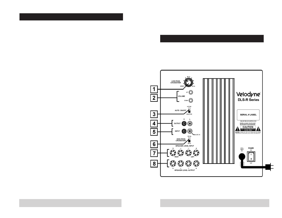
Figure 1. DLS-3500R, DLS-3750R and DLS-4000R
Rear Panel Connections