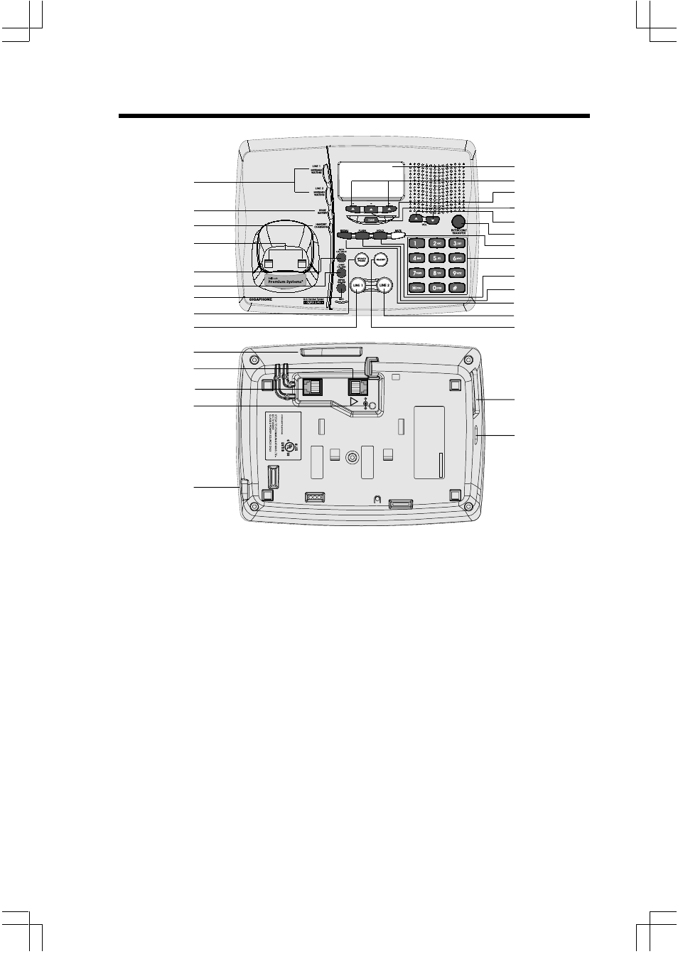
The base unit layout – VTech 2432 User Manual
Page 6
6
1.
Message Waiting Indicator
(Line1,Line2)
2.
Spare Battery Indicator
3.
Charge Indicator
4.
Charging Contacts
5.
Auto Callback Key
6.
3-Way Calling Key
7.
Repeat Dialing Key
8.
Speakerphone Key
9.
Line 1 Key
10.
Data Jack
11.
Line 1 Jack
12.
Line 2 Jack
13.
DC Connector
14.
Headset Jack
15.
LCD Display
16.
Scroll Keys
17.
Select Key
18.
Clear Key
19.
Volume Keys
20.
Intercom/Transfer Key
21.
Mute Key
22.
Dialing Keys (0-9,*,#)
23.
Hold Key
24.
Flash Key
25.
Redial Key
26.
Line 2 Key
27.
Headset Key
28.
Spare Battery Drawer
29.
Spare Battery Release
The Base Unit Layout
1
16
17
8
9
4
5
18
20
19
21
22
23
24
25
2
3
15
26
27
6
7
LINE 2
LINE 1/
L1 + L2
7V DC
!
COMPLIES WITH 47 CFR P
A
R
T 68
REGISTRA
TION NO
.: US: EW7 WI00B80-513700
RINGER EQUIV
A
LENCE:
0.0B
USOC J
ACK:
RJ1
1C
, RJ14C
THIS
DEVICE
COMPLIES
WITH
PAR
T 15
OF
T
HE
FCC
R
U
LES
. OPERA
TION
IS SUBJECT
T
O
THE FOLLO
WING
TW
O
CONDITIONS:
1)THIS DEVICE MA
Y
NO
T
CA
USE
HARMFUL
INTERFERENCE;
AND
2
) THIS
DEVICE
MUST
A
CCEPT
A
NY
INTERFERENCE
R
ECEIVED
,
INCLUDING
INTERFERENCE
THA
T MA
Y
CA
U
SE UNDESIRED OPERA
TION.
PRIV
A
C
Y
OF
COMMUNICA
TIONS
M
AY
N
O
T
BE
ENSURED
W
HEN
USING
THIS PHONE.
MODEL :
20-2432
VTECH
TELECOMMUNICA
TIONS L
TD
.
MANUF
AC
TURED IN CHINA
FCC ID:
EW780-5001-00
HA
C
12
13
14
11
10
28
29