Appendix f, Electrical connection diagrams, Page 19 – Venmar 700 cfm User Manual
Page 19
Page 19
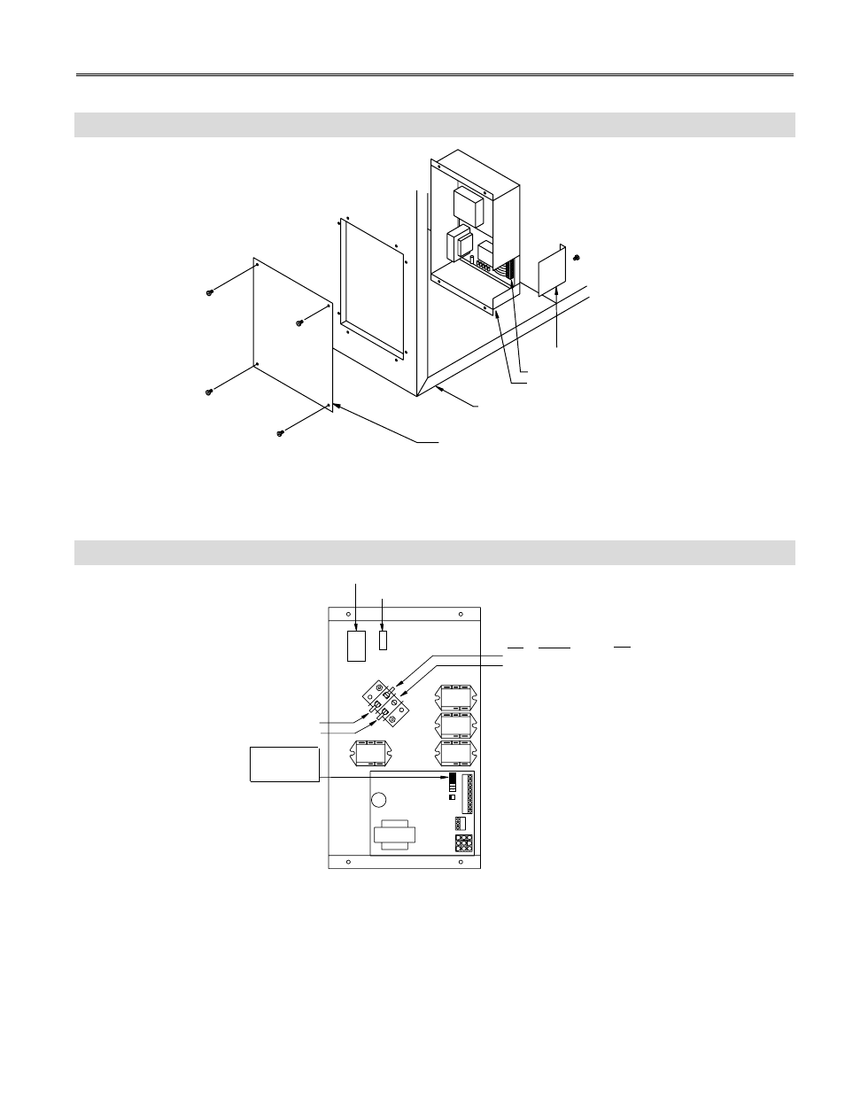
Control cover plate
Control box
Remote control access plate
Remote wiring terminal block
HRV Cabinet
VE0001A
R
ed
Low Speed (Red)
Remove power
before installing
or removing
JU1-F Extended
Defrost Jumper
12 pin
2 pin
Med Speed (Blue)
Low To Medium, move the fork connector:
To change the minimum speed setting from
from here
to here
LOW SPEED SETTING
321
FF1
YRGB
OL
1J
2
J4
JU1
ABCDEFG
J3
4
7
6
9
OC
VE0004A
Low Speed Setting Wire Connections 600 cfm and 1200 cfm
Appendix F
Electrical Connection Diagrams
Control Box Assembly 600 cfm and 1200 cfm