Vanguard Heating POWERMAX PM200 User Manual
Page 22
20
APPENDIX A
TYPICAL SPECIAL STAINLESS STEEL VENTING
For use with Category II, III, IV appliances
Contact Local Building or Fire Officials About Restrictions and Installation Inspections in your area as well as National codes:
USA -National fuel gas code ANS1-Z223.l
CANADA -CAN\CGA-B 149.1 or .2 Fuel Burning Installation Code
Please refer to appliance manufacturers’ instructions to determine proper sizing and connection of venting system to appliance, including
maximum horizontal length, maximum height, and installation clearances (air spaces). The proper operation of the vent system and
appliance requires parts specified by Z-FLEX with no deletions or substitutions. NOTE: Co-venting with other appliances is prohibited
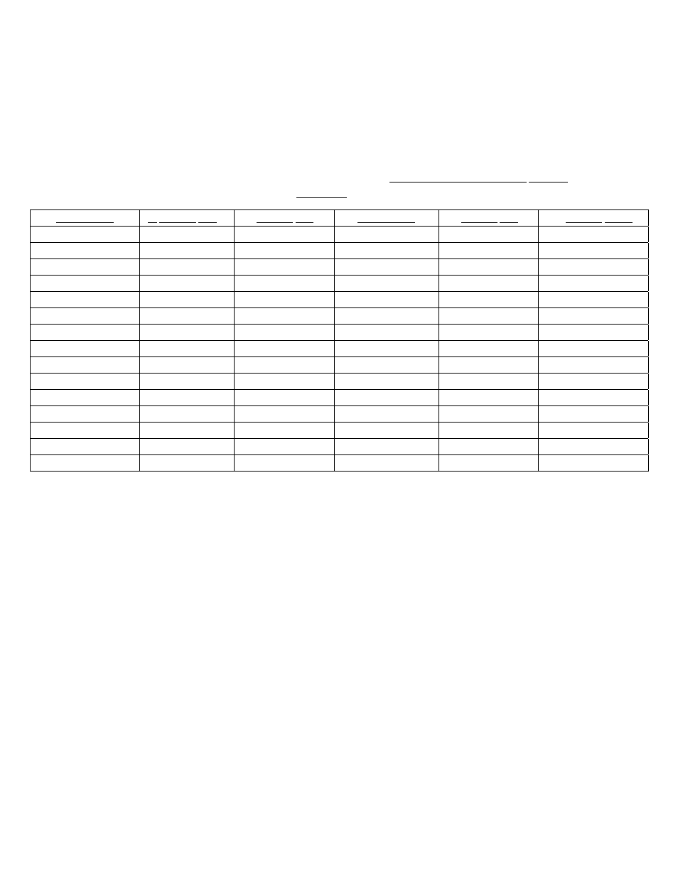
PARTS LIST
COMPONENT 3” SYSTEM CAT. #
4” SYSTEM CAT. #
COMPONENT 3”
SYSTEM CAT. #
4” SYSTEM CA1~#
10 FOOT PIPE
SVEPWC0310
SVEPWC04I0
ADJUST. FLASHING
SVSADJ03 SYSADJ04
8 FOOT PIPE
SVEPWC0308
SVEPWC0408
REDUCER 4” TO 3”
SVSERWC0403 SVSR0404
5 FOOT PIPE
SVEPWC0305
SVEPWC0405
FLAT FLASHING
SVSSCS03 SVSSCS04
4 FOOT PIPE
SVEPWC0304
SVEPWC0404
LOCKING BAND
SVSLBX03 SVSLBX04
3 FOOT PIPE
SVEPWC0303
SVEPWC0403
FIRESTOP SUPPORT
SVSFSS03
SVSFSS04
2 FOOT PIPE
SVEPWC0302
SVEPWC0402
FTRESTOP SPACER
SVSFSX03
SVSFSX04
1 FOOT PIPE
SVEPWC0301
SVEPWC0401
TERMINATION TEE
SVSTTX03 SVSTTX04
6 INCH PIPE
SVEPWC03.5
SVEPWCO4.5
TERMINATION BOX
SVSRTX03 SVSRTX04
90
0
ELBOW SVEEWC0390
SVEEWC0490 RAIN CAP
SVSRCX03 SVSRCX04
45 ELBOW
SVEEWC0345
SVEEWC0345
TOP SUPPORT
SVSLSX03
SVSLSX04
HORJZ. DRAIN TEE
SVEDWC03
SVEDWC04
STORM COLLAR
SVSSCX03
SVSSCX04
VERTICAL DRAIN TEE
SVEVWC03
SVEVWC04
Z-VENT SEALANT
GE106X
WALL THIMBLE
SVSWTX03
SVSWTX04
WM TERM COUPLING
SVSTPX03
WM GV STARTER
SVEWMG03
AMETEK FAN CONN.
SVSACA03
DRAIN TUBE KIT
SVEDTK
WM CGI STARTER
SVEWMFA03
Z-FLEX recommends that the installation be performed by an experienced professional who works with venting systems on a-regular
basis. These instructions are intended as a guide to assist a professional installer.
When the Z-VENT system is installed, the following should be observed:
1.
A venting system that exits the structure through a sidewall or the like, shall terminate not less than 12 inches (254 mm) above the ground
(see illustration # 2, page 4).
2.
The termination of a system shall be located above the snow line in geographical areas where snow accumulates. The termination area
should be kept clear of snow and ice at all times.
3.
The vent shall not terminate less than 7 ft. (2.13 m) above a paved sidewalk or driveway.
4.
The termination shall be 6 ft. (1.8 m) or more from the combustion air intake of any appliance.
5.
The system shall terminate more than 3 ft. (.91 m ) from any other building opening, gas utility meter, service regulator or the like.
6.
Exterior mounted venting systems should be enclosed below the roof line with a chase to limit condensation and protect against
mechanical failure.
NOTES:
A.
The Z-FLEX SPECIAL STAINLESS VENT SYSTEM is for use only with appliances having a positive vent pressure of 3” of water column
or less.
B.
Except for installation in one and two family dwellings, a venting system that extends through any zone above that on which the connected
appliance is located shall be provided with an enclosure having a fire resistance rating equal to or greater than that of the floor or roof
assemblies through which it passes
C.
Do not place any type of insulation in any required air spaces surrounding the venting system.
D.
A termination must be used on all installations to assure proper operation and to prevent debris from entering the venting system.