Divatop hc, 34 en – FERROLI Divatop H C User Manual
Page 34
DIVAtop HC
34
EN
cod. 3540S840 - 02/2010 (Rev. 00)
Table of faults
Table. 2
5. TECHNICAL DATA AND CHARACTERISTICS
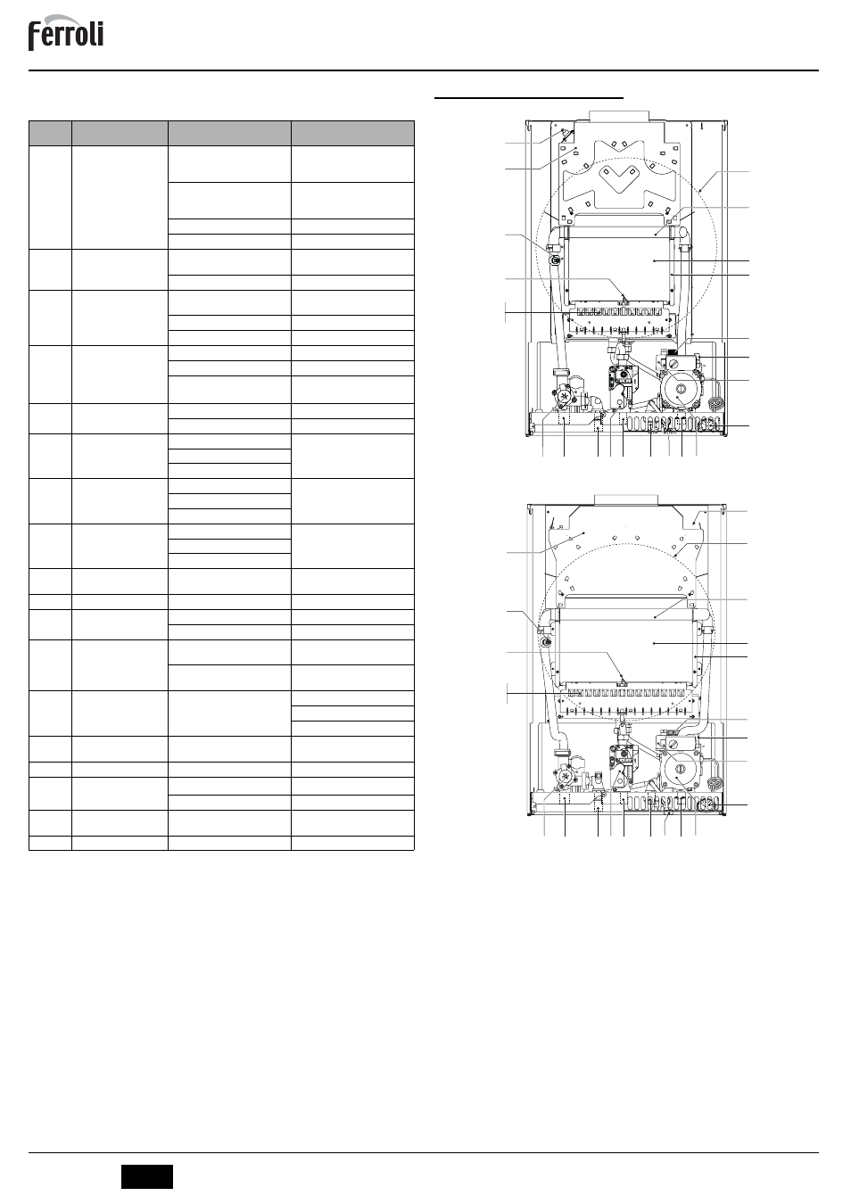
5.1 General view and main components
fig. 22 - General view DIVAtop HC 24
fig. 23 - General view DIVAtop HC 32
7
Gas inlet
10
System delivery
11
System return
14
Safety valve
19
Combustion chamber
20
Burner assembly
21
Main nozzle
22
Burner
26
Combustion chamber insulation
27
Copper exchanger
32
Heating circulating pump
36
Automatic air vent
44
Gas valve
56
Expansion tank
74
System filling cock
78
Anti-backflow device
81
Ignition and detection electrode
95
Diverter valve
126
Fume thermostat
145
Pressure gauge
209
Hot water tank delivery
210
Hot water tank return
246
Pressure transducer
278
Double sensor (Safety + Heating)
Code
fault
Fault
Possible cause
Recommended cure
A01
No burner ignition
No gas
Check the regular gas flow to the
boiler and that the air has been
eliminated from the pipes
Ignition/detection electrode fault
Check the wiring of the electrode
and that it is correctly positioned
and free of any deposits
Defective gas valve
Check and change the gas valve
Ignition power too low
Adjust the ignition power
A02
Flame present signal with
burner off
Electrode fault
Check the ionisation electrode
wiring
Card trouble
Check the card
toA03
Over-temperature
protection trips
Heating sensor damaged
Check the correct positioning and
operation of the heating sensor
No water circulation in the system
Check the circulator
Air in the system
Vent the system
F04
Fume thermostat
activated (after activation of
the fume thermostat, boiler
operation is prevented for
20 minutes)
Fume thermostat contact open
Check the thermostat
Wiring disconnected
Check the wiring
Flue not correctly sized or
obstructed
Change the flue
A06
No flame after the ignition
phase
Low pressure in the gas system
Check the gas pressure
Burner minimum pressure setting
Check the pressures
F10
Delivery 1 sensor fault
Sensor damaged
Check the wiring or replace the
sensor
Wiring shorted
Wiring disconnected
F11
Tap water sensor fault
Sensor damaged
Check the wiring or replace the
sensor
Wiring shorted
Wiring disconnected
F14
Delivery 2 sensor fault
Sensor damaged
Check the wiring or replace the
sensor
Wiring shorted
Wiring disconnected
F34
Supply voltage under
170V.
Electric mains trouble
Check the electrical system
F35
Irregular mains frequency
Electric mains trouble
Check the electrical system
F37
Incorrect system water
pressure
Pressure too low
Fill the system
Sensor damaged
Check the sensor
F39
External sensor fault
Probe damaged or wiring shorted
Check the wiring or change the
sensor
Sensor disconnected after activat-
ing the sliding temperature
Reconnect the external sensor or
disable the sliding temperature
F40
Incorrect system water
pressure
Pressure too high
Check the system
Check the safety valve
Check the expansion tank
A41
Sensor positioning
Delivery sensor detached from pipe
Check the correct positioning and
operation of the heating sensor
F42
Heating sensor fault
Sensor damaged
Change the sensor
F43
Exchanger protection trips.
No system H
2
O circulation
Check the circulator
Air in the system
Vent the system
F47
System water pressure
sensor fault
Wiring disconnected
Check the wiring
F50
Modureg fault
Wiring disconnected
Check the wiring
44
32
246
36
14
26
19
27
56
78
81
20
21
22
278
95
10
209
7
210
11
145
74
126
44
32
246
36
14
26
19
27
56
78
81
20
21
22
278
95
10
209
7
210
11
145
74
126