Installation and connection, Installing procedure – TOA Electronics W-906A User Manual
Page 5
4. INSTALLATION AND CONNECTION
Installing this amplifier requires the optional back box, which is Model BX-9F for flush mounting in any 4 inch
wall and Model BX-9S for surface mounting.
Fix the back box first in installing the amplifier...
Installing Procedure
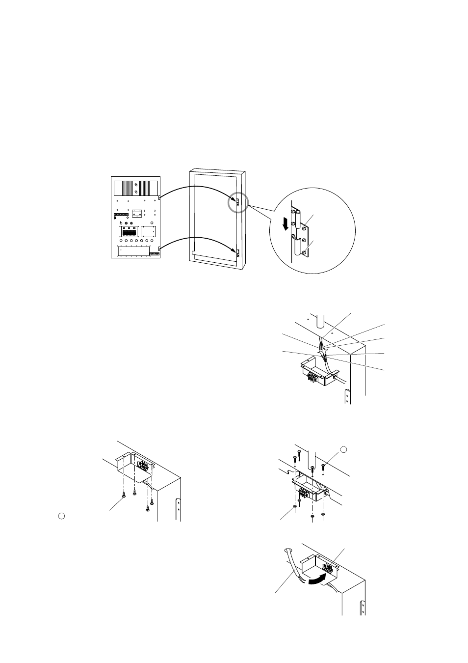
Step 1. Attach hinges to the back box by means of screws. (The hinges and screws are accessories supplied
free of change.)
Step 2. Fix the amplifier to the back box by inserting the amplifier bolts into the hinges as illustrated.
Step 3. Connecting power cable
Be sure to make proper cable connections according to
color cording of the power cable.
After connection is completed, insulate sufficiently the
jointed sections and put them in a junction box.
Step 4. Attaching the junction box to the back box
The BX-9F differs from the BX-9S in the way to attach the junction box to the back box.
Step 5. Connecting the speaker cable
Connect the speaker cable to the speaker terminals on
the junction box. Amplifier output impedance may be
selected at the output terminals on the front panel.
5
From indoor wiring
Junction Box
BLACK
GREEN
GREEN
WHITE
BLACK
WHITE
M3 x 10 screw (4 pcs)
Nut M3 (4 pcs)
+
M3 x 8 Tapping screw
(4 pcs)
+
SPEAKER TERMINAL
Class 2 Wiring
may be used.
SPEAKER CORD
INPUT 1
POWER
ON
250V 3A
250V 6A
OFF
OFF
MAX
INPUT 2
INPUT 3
AC FUSE
OFF
ON
LOW PASS
OFF
ON
HIGH PASS
OUT
63
125
250
500
1k
2k
4k
8k
16k
63
125
250
500
1k
2k
4k
8k
16k
IN
EQUALIZER
OUTPUT FUSE
COMPRESSOR
INPUT 4
INPUT 5
INPUT 6
MASTER
12
6
0
6
12
12
6
0
6
12
Amplifier
(main chassis)
Back Box
BX-9F, BX-9S
HINGE
M3 x 6 mm
(6 pcs)
[BX-9F]
[BX-9S]