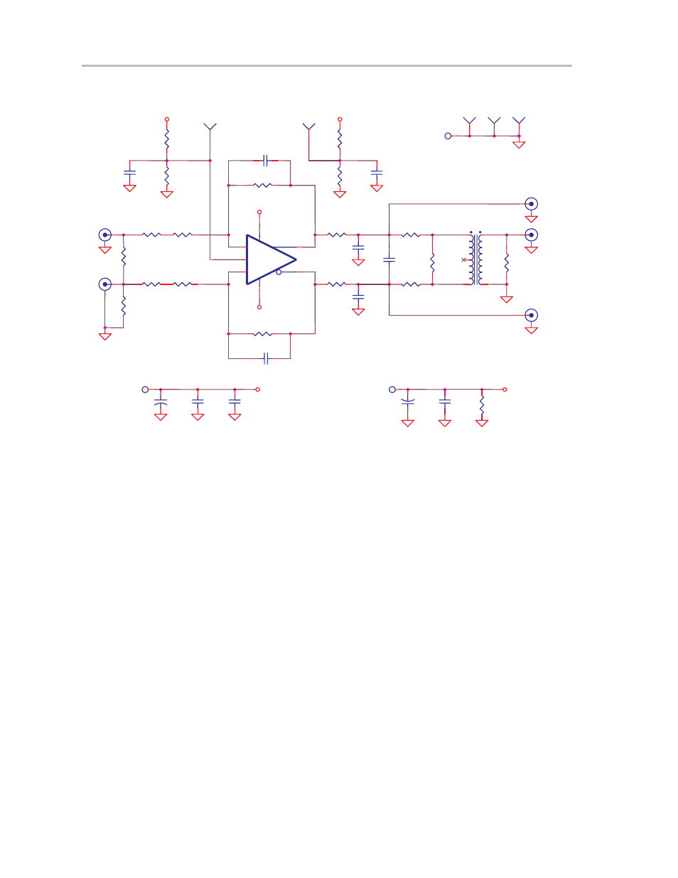
Figure 5−3. schematic diagram – Texas Instruments THS4503EVM User Manual
Page 28
5-4
Figure 5−3. Schematic Diagram
C2 0
VCC+
C4 *
R17
0
R8
340
Ω
R5
392
Ω
R13
*
C10
*
R3
402
Ω
−
Vocm
+
U1
THS4503
1
8
2
3
6
5
4
J8
+VS
T1
ADP4
−1WT
6
1
5
4
3
R2
374
Ω
TP1
Vocm
+VS
−VS
J6
Vin+
R12
*
J1
Vin−
C12
0.1
µ
F
TP4
C5
*
TP5
R11
*
R16
*
R4
392
Ω
J4
Vout
−VS
C3*
R14
*
R15
*
C7
*
+
C8
6.8
µ
F
C1 0
J2
Vout+
+VS
J3
Vout−
R7 0
C6
*
TP2
PD−
J5
−VS
VCC+
R1
56.2
Ω
J7
GND
C13
1
µ
F
R9
340
Ω
R10
280
Ω
TP3
C9
0.1
µ
F
+
C11
6.8
µ
F
C14
*
R6 0
Note:
Devices designated with an
*
are not installed on the EVM. The user must supply these components.
See also other documents in the category Texas Instruments Receivers and Amplifiers:
- THS4151 (26 pages)
- TRF1500 (74 pages)
- SLOU082 (28 pages)
- TAS5508-5121K8EVM (24 pages)
- TPA6102A2 (16 pages)
- TPA3001D1EVM (22 pages)
- TPA6030A4 (25 pages)
- TPA701 (26 pages)
- TPA6110A2 MSOP (18 pages)
- TAS5727 (21 pages)
- TPA005D02 (50 pages)
- SLOU121 (42 pages)
- TPA0243 (20 pages)
- TPA0253 (20 pages)
- TPA102 MSOP (26 pages)
- THS4131 (26 pages)
- SLOU020A (28 pages)
- TPA751 MSOP (20 pages)
- TPA005D12 (44 pages)
- TPA6139A2 EVM (8 pages)
- TPA0103 (32 pages)
- SLOU106 (26 pages)
- THS4141 (26 pages)
- THS3001 (20 pages)
- TPA0233 (20 pages)
- TPA2008D2 (26 pages)
- 2004 (20 pages)
- TPA3003D2 (36 pages)
- SLAU081 (44 pages)
- TPA301 (28 pages)
- TPA3100D2 (11 pages)
- SLOU023A (26 pages)
- TAS5110D6REF (45 pages)
- TA5704EVM (27 pages)
- TAS5518 (20 pages)
- APA100 (42 pages)
- TPA3200D1 (30 pages)
- TAS5066PAG (22 pages)
- TPA6204A1 (16 pages)
- THS4150 (26 pages)
- TPA311 (28 pages)
- TPA3008D2 (31 pages)
- TPA6101A2 (16 pages)