Assembly step, Step 01, Step 02 – Trojan SOLO 200 User Manual
Page 6: Step 03
1529AU-6
ASSEMBLY STEP
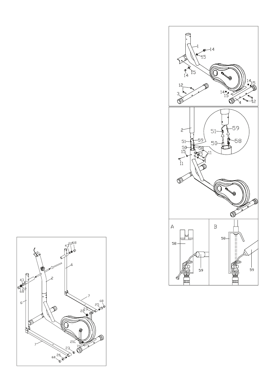
STEP 01
• Attach the FRONT STABILIZER (3) to the MAIN FRAME (1) with the
SCREWS (12), arc WASHERS (15) and CAP NUTS (14 ).
• Then attach the REAR STABILIZER (4) to the MAIN
FRAME (1) with CARRIAGE BOLT (12) , ARC WASHERS (15) and CAP
NUTS (14).
STEP 02
• Connect the SENSOR WIRE (50) in the MAIN FRAME (1) with the
EXTENSION WIRE (51) on the UPRIGHT TUBE (2).
• Get the TENSION CABLE (59) out of the MAIN FRAME (1), and con-
nect it with wire on the TENSION CONTROLLER (58) as step belowe:
Step 2.1: Put the CABLE END (58) into the SPRING HOOK (59).(pic A)
Step 2.2: Pull the knob and force the SHORT CABLE (58) into the GAP
OF THE BRACKET (59). (pic B)
• Tension is increased by turning the knob clockwise.
• Insert the UPRIGHT TUBE (2) into the MAIN FRAME and fix it with
SCREWS ( 11) and are WASHERS (15)
STEP 03
• Take off the NUT CAPS (68), NYLON NUTS (22) and WASHERS (43).
Attach the SLEEVES (6) to the UP RIGHT TUBE (2) with the WASH-
ERS (43) and NYLON NUTS(22).
• Take off the NYLOCK NUTS (76), and attach the other one end of the
PEDAL TUBES (7) onto the CRANK (21)with the NYLOCK NUTS (76)
and screw driver.