Panels layout – Tripp Lite U224-4R4-R User Manual
Page 5
OUTPUT
DC 5V
OUTPUT
OUTPUT
OUTPUT
OUTPUT
OUTPUT
OUTPUT
OUTPUT
DC 5V
5
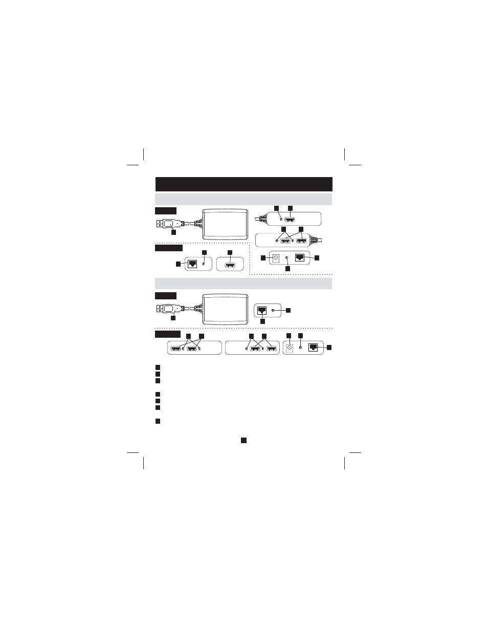
6. Panels Layout
6.2 U224-4R4-R
6.1 U224-1R4-R
1
1 ft. USB 2.0 Type A Cable
2
RJ45 Port — Connect the Local Unit to the Remote Unit using Cat5e/6 cable
3
Link LED — A red LED on the Remote Unit that indicates the Local and
Remote Units are connected using Cat5e/6 cable
4
USB Port
5
Power Jack — The included AC Adapter connects here
6
Power LED — A red LED that indicates the local unit is connected to a
powered-on computer. (U224-4R4-R only)
7
USB Port LED — A green LED that indicates a USB device is connected to
the corresponding port. (The USB LED for the U224-1R4-R Remote USB Port
is located between the RJ45 Port and Power Jack on the Local Unit)
1
1
2
2
2
2
6
6
3
7
7
7
4
4
4
5
5
Local Unit
Remote Unit
Remote Unit
Local Unit
7
7
4
Side A
Side B
4
200808024 2836.indd E5
200808024 2836.indd E5
9/23/2008 10:15:31 AM
9/23/2008 10:15:31 AM
- IBAR12-20ULTRA (4 pages)
- 2-PORT COMPACT DVI USB B004-DUA2-K-R (1 page)
- WEXT5-B072-016 (2 pages)
- Network Dataline Surge Suppressors DHUB (12 pages)
- SVGA 1-to-4 Splitter B114-0H4 (5 pages)
- HDMI v1.3 Splitter B118-302-R (2 pages)
- TLM1015NC (3 pages)
- NETCOMMANDERTM B072-008-1 (24 pages)
- OmniSmart USB (13 pages)
- PM6NS (3 pages)
- HT706TSAT (4 pages)
- ISOBAR12ULTRA (4 pages)
- B006-004-R (19 pages)
- IBAR 12 (16 pages)
- 200401086 (3 pages)
- 602 (3 pages)
- SPS-615-HG (3 pages)
- B051-000 IP (65 pages)
- B004-008 (9 pages)
- ISOBLOK (12 pages)
- U215-004-R (8 pages)
- SUPER 10+TEL DELUXE (12 pages)
- B020-U08-19-K (8 pages)
- B119-302-R (3 pages)
- DB25-PAR (2 pages)
- P776-019 (2 pages)
- PK3021LI (2 pages)
- SRC-2X (19 pages)
- NC2004EC (2 pages)
- B020-008 (1 page)
- IP CAT5 B072-016-1-IP (32 pages)
- B064-032-04-IP (2 pages)
- IBRM 12/15A-L20P (4 pages)
- SmartPro USB (8 pages)
- DG206 (3 pages)
- Power Accessory Module PAM-3 (2 pages)
- DEU2TEL (2 pages)
- PK3022ET (2 pages)
- MT-6PLUS (4 pages)
- B022-004-R (13 pages)
- P036-002 (2 pages)
- B013-330 (3 pages)
- SUPER5DEU (3 pages)
- P772-015 (2 pages)
- TOUCHMASTER MT-6 (8 pages)