TRENDnet BE1-87G User Manual
Page 13
BE1-87G - Human Machine Interface (Controls And Indicators)
2-1
SECTION 2 • HUMAN MACHINE INTERFACE
(Controls And Indicators)
DESCRIPTION
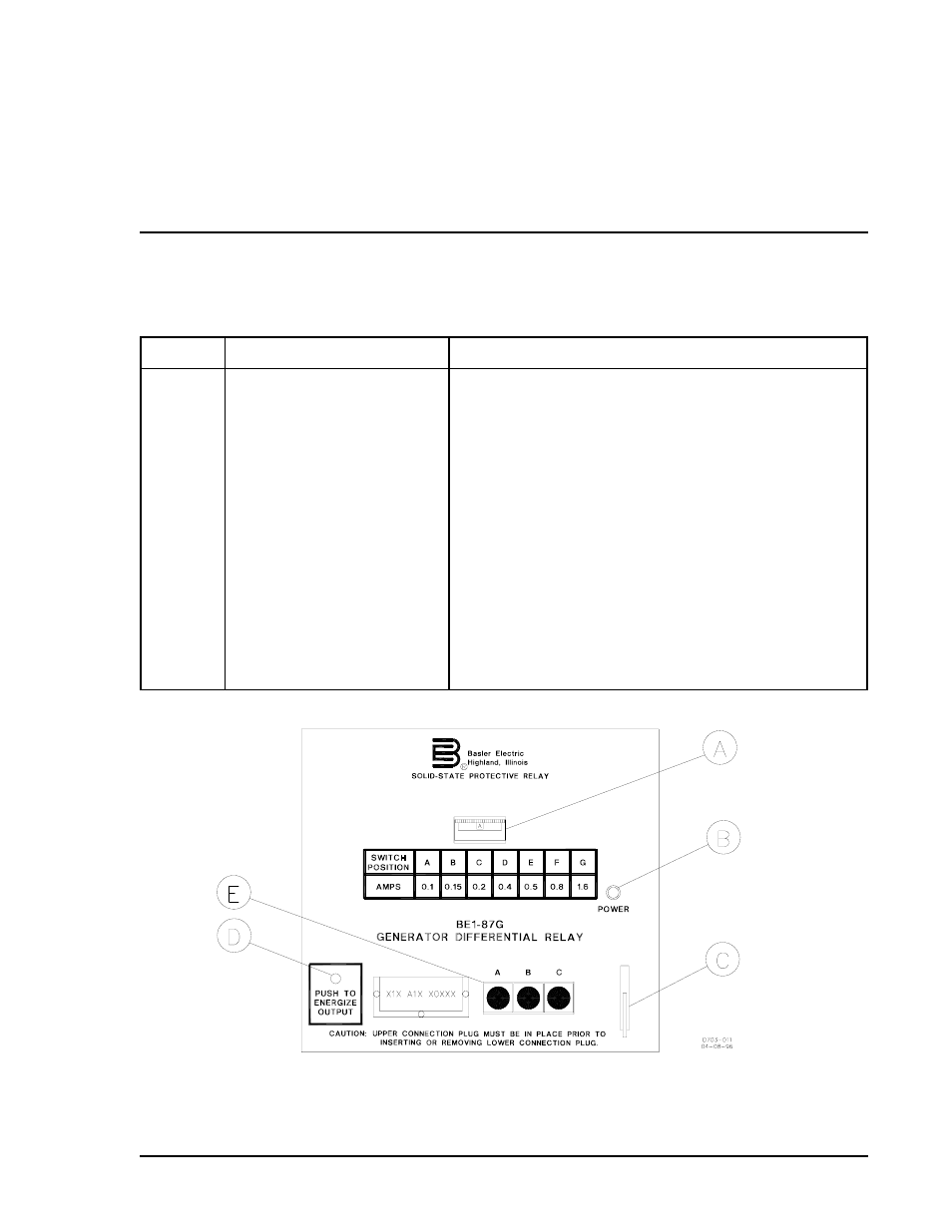
Table 2-1 lists and briefly describes the BE1-87G Variable Percentage Differential Relay operator controls
and indicators. Reference the call-out letters to Figure 2-1.
Table 2-1. BE1-87G Controls and Indicators (Refer to Figure 2-1)
Locator
Control or Indicator
Function
A
Sensitivity Switch
Establishes reference for the operating current. It is a
seven position thumbwheel switch labeled A through G.
The chart below the switch relates the switch position to
the operating current required for tripping when the
restraint current is
nominal (five amperes, sensing input
range one, and one ampere, sensing input range two).
B
Power Indicator
LED illuminates to indicate power supply is operating.
C
Target Reset Lever
(Optional)
Linkage extends through bottom of front cover to reset
magnetically latching target indicators.
D
PUSH-TO-ENERGIZE Switch
(Optional)
A momentary contact pushbutton switch accessible by
inserting a 1/8" diameter non-conducting rod through the
front panel. Operates the output and auxiliary relays.
E
Target Indicators
(Optional)
Magnetically latching indicators which indicate the
associated phase that has caused a trip.
NOTE: Above panel for 3
L
units only.
Figure 2-1. Location of Controls and Indicators, BE1-87G, Sensing Input Range 1