5 options and accessories, 6 wiring diagram – Therma-Stor Products Group Phoenix 200 HT User Manual
Page 7
7
www.thermastor.com • [email protected]
Toll-Free 1-800-533-7533
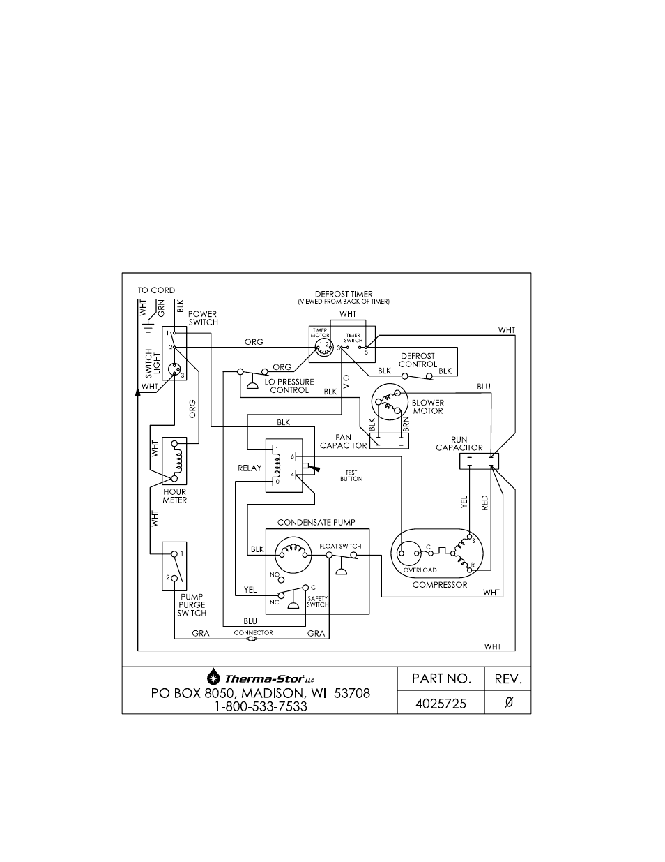
Figure 8: Wiring diagram
4.7 Relay
The contacts of the single pole, single throw relay
complete the power circuit to the compressor. The
contacts are closed when power is provided to the relay
coil via the control circuit. The control circuit includes the
power switch, low pressure control, defrost thermostat and
timer.
5 Options and Accessories
4024682
Air Filter, Pleated, 2” x 6” x 20”
57% MERV-8
4024750
Intake Flex Duct
2” x 25” Metalized Polyester
4024935
Lay-Flat Duct, 0” Round x 250’ Roll
6 Wiring Diagram