3 pwm interface (j140) – Texas Instruments TAS5026REF User Manual
Page 17
2-5
2.3
PWM Interface (J140)
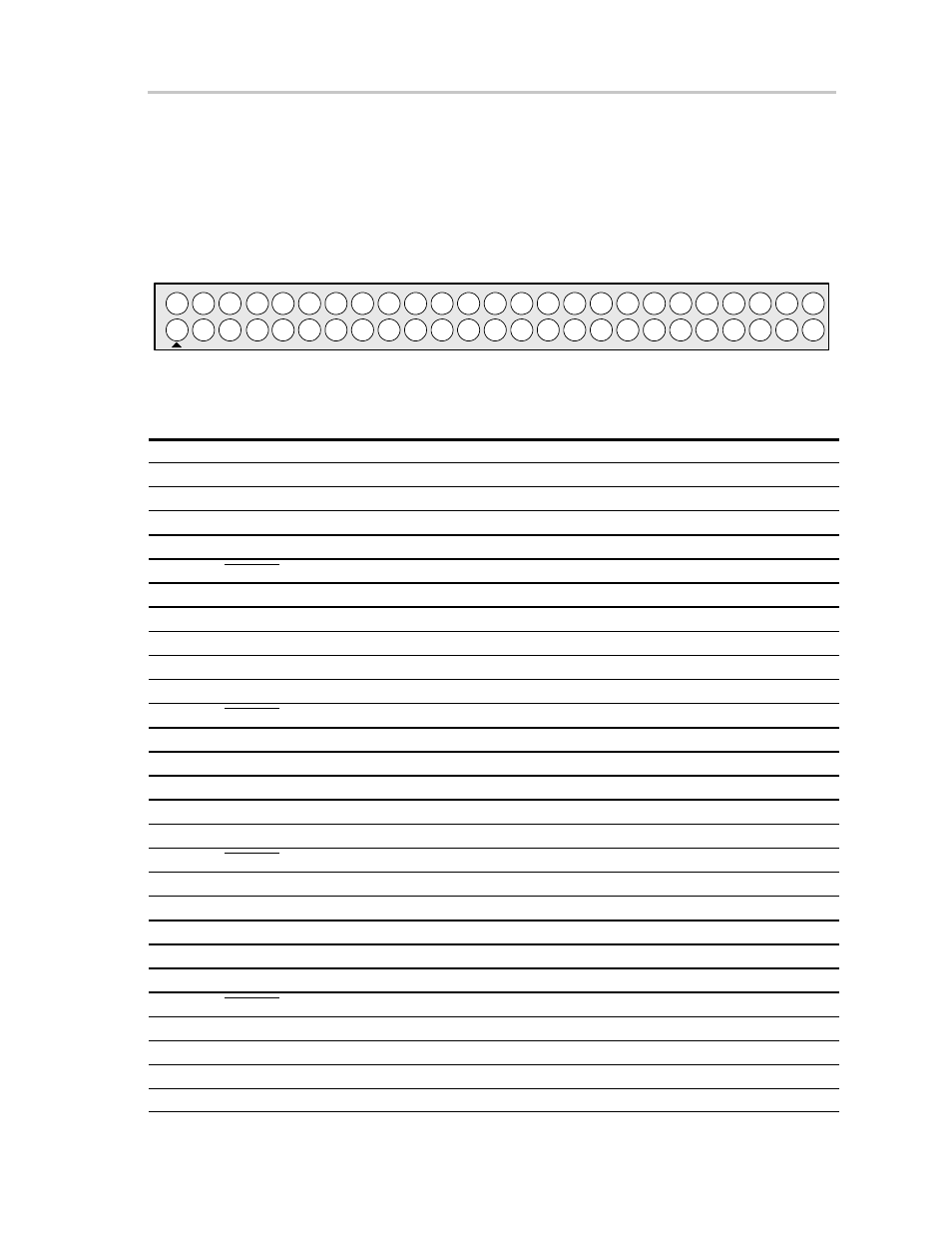
The PWM interface connects the TAS5026REF board to the output stage
module.
Figure 2–1. Pin Numbers at PWM Interface (J140)
2
3
1
5
6
4
8
9
7
10
12
13
11
15
16
14
18
19
17
20
22
23
21
25
26
24
28
29
27
30
32
33
31
35
36
34
38
39
37
40
42
43
41
45
46
44
48
49
47
50
Table 2–4. J140 Pin Description
Pin No.
Net Name
Description
01
V-HBRIDGE-CONTROL
For future use
02
GND
Ground
03
PWM–AP–1
Channel 1 PWM input (differential +) – positive H-bridge side
04
PWM–AM–1
Channel 1 PWM input (differential –) – positive H-bridge side
05
VALID–1
Valid channel 1
06
PWM–BM–1
Channel 1 PWM input (differential –) – negative H-bridge side
07
PWM–BP–1
Channel 1 PWM input (differential +) – negative H-bridge side
08
GND
Ground
09
PWM–AP–2
Channel 2 PWM input (differential +) – positive H-bridge side
10
PWM–AM–2
Channel 2 PWM input (differential –) – positive H-bridge side
11
VALID–2
Valid channel 2
12
PWM–BM–2
Channel 2 PWM input (differential –) – negative H-bridge side
13
PWM–BP–2
Channel 2 PWM input (differential +) – negative H-bridge side
14
GND
Ground
15
PWM–AP–3
Channel 3 PWM input (differential +) – positive H-bridge side
16
PWM–AM–3
Channel 3 PWM input (differential –) – positive H-bridge side
17
VALID–3
Valid channel 3
18
PWM–BM–3
Channel 3 PWM input (differential –) – negative H-bridge side
19
PWM–BP–3
Channel 3 PWM input (differential +) – negative H-bridge side
20
GND
Ground
21
PWM–AP–4
Channel 4 PWM input (differential +) – positive H-bridge side
22
PWM–AM–4
Channel 4 PWM input (differential –) – positive H-bridge side
23
VALID–4
Valid channel 4
24
PWM–BM–4
Channel 4 PWM input (differential –) – negative H-bridge side
25
PWM–BP–4
Channel 4 PWM input (differential +) – negative H-bridge side
26
GND
Ground
27
PWM–AP–5
Channel 5 PWM input (differential +) – positive H-bridge side