3 input and output setup – Texas Instruments THS4150 User Manual
Page 19
2-3
Using the THS4150 EVM
2.3
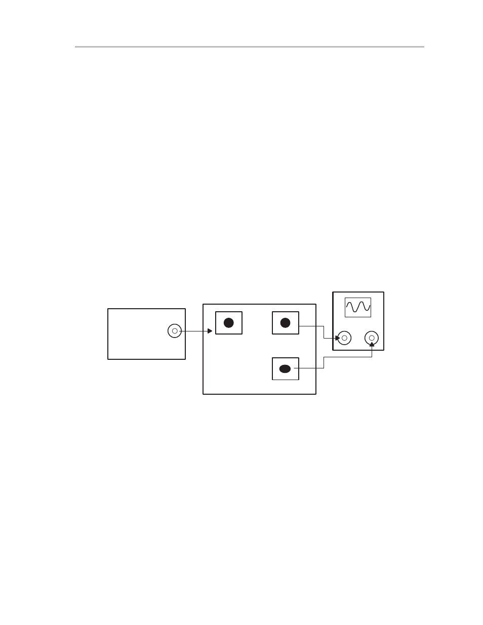
Input and Output Setup
1) Ensure that JU3, JU4, and JU1 are
not installed (open circuit).
2) Set the function generator to generate a 1 MHz,
±
0.5 V (1 V
PP
) sine wave
with no dc offset.
3) Turn off the function generator before proceeding to the next step.
4) Using a BNC-to-SMA cable, connect the function generator to J1 (V
I+
) on
the EVM.
5) Using a BNC-to-SMA cable, connect the oscilloscope to J3 (V
O–
) on the
EVM.
6) Using a BNC-to-SMA cable, connect the oscilloscope to J4 (V
O+
) on the
EVM. Set the oscilloscope to 0.5 V/division and a time-base of 0.2
µ
s/division.
Note: The oscilloscope must be set to use a 50-
Ω
input impedance for
proper results.
Figure 2–2. Signal Connections
OUT
1 MHz
1 V
PP
0 V Offset
50
Ω
Source
Impedance
J1 V
in+
J3 V
out–
J4 V
out+
CH-1
CH-2
THS4150 EVM
FUNCTION
GENERATOR
OSCILLOSCOPE
50
Ω
Impedance
Figures are not drawn to scale.
- THS4151 (26 pages)
- TRF1500 (74 pages)
- SLOU082 (28 pages)
- TAS5508-5121K8EVM (24 pages)
- TPA6102A2 (16 pages)
- TPA3001D1EVM (22 pages)
- TPA6030A4 (25 pages)
- TPA701 (26 pages)
- TPA6110A2 MSOP (18 pages)
- TAS5727 (21 pages)
- THS4503EVM (28 pages)
- TPA005D02 (50 pages)
- SLOU121 (42 pages)
- TPA0243 (20 pages)
- TPA0253 (20 pages)
- TPA102 MSOP (26 pages)
- THS4131 (26 pages)
- SLOU020A (28 pages)
- TPA751 MSOP (20 pages)
- TPA005D12 (44 pages)
- TPA6139A2 EVM (8 pages)
- TPA0103 (32 pages)
- SLOU106 (26 pages)
- THS4141 (26 pages)
- THS3001 (20 pages)
- TPA0233 (20 pages)
- TPA2008D2 (26 pages)
- 2004 (20 pages)
- TPA3003D2 (36 pages)
- SLAU081 (44 pages)
- TPA301 (28 pages)
- TPA3100D2 (11 pages)
- SLOU023A (26 pages)
- TAS5110D6REF (45 pages)
- TA5704EVM (27 pages)
- TAS5518 (20 pages)
- APA100 (42 pages)
- TPA3200D1 (30 pages)
- TAS5066PAG (22 pages)
- TPA6204A1 (16 pages)
- TPA311 (28 pages)
- TPA3008D2 (31 pages)
- TPA6101A2 (16 pages)