Warning, Maintenance and repair instructions – Troy-Bilt TB425CS User Manual
Page 20
20
MAINTENANCE AND REPAIR INSTRUCTIONS
Adjusting Nuts
Feeler Gauge
Rocker Arms
Fig. 66
Fig. 67
Feeler Gauge
Exhaust
Adjusting Nut
Exhaust
Rocker Arm
Exhaust
Clearance:
.003-.006 in.
(.076-0.152 mm)
Exhaust Valve Stem
10. If the clearance is not within specification:
a. Turn the adjusting nut using a 5/16 inch (8 mm)
wrench or nut driver (Fig. 67).
• To increase clearance, turn the adjusting nut
counterclockwise.
• To decrease clearance, turn the adjusting nut
clockwise.
b. Recheck both clearances, and adjust as necessary.
11. Reinstall the rocker arm cover using a new gasket.
Torque the screw to 20–30 in
•
lb (2.2–3.4 N
•
m).
12. Reinstall the engine cover. Check alignment of the
cover before tightening the screws. Tighten screws.
13. Reinstall the muffler cover. Slip the rear tab on the
muffler cover into the engine cover rear slot. Then
slide the remaining slots into the tabs until they snap
into place (Fig. 62).
14. Check the spark plug and reinstall. See Replacing
the Spark Plug.
15. Replace the spark plug wire.
INTAKE
EXHAUST
Intake Valve
Stem
Intake Clearance:
.003–.006 in.
(.076–0.152 mm)
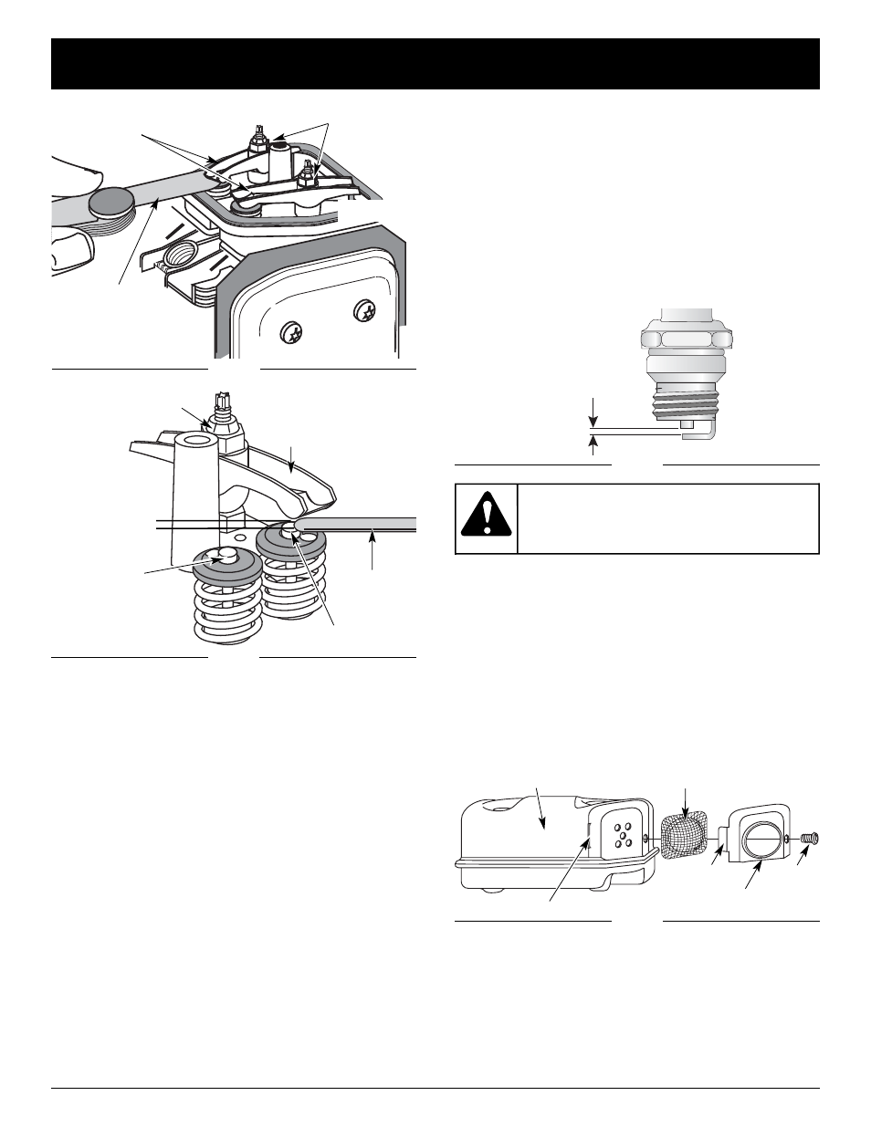
0.025 in.
(0.655 mm.)
REPLACING THE SPARK PLUG
Use a replacement part number 180890 spark plug. The
correct air gap is 0.025 in. (0.655 mm.). Remove the plug
after every 25 hours of operation and check its
condition.
1. Stop the engine and allow it to cool. Grasp the plug
wire firmly and pull the cap from the spark plug.
2. Clean dirt from around the spark plug. Remove the
spark plug from the cylinder head by turning a 5/8 in.
socket counterclockwise.
3. Replace cracked, fouled or dirty spark plug. Set the air
gap at 0.025 in. (0.655 mm.) using a feeler gauge (Fig. 68).
Fig. 68
4. Install a correctly-gapped spark plug in the cylinder
head. Turn the 5/8 in. socket clockwise until snug.
If using a torque wrench torque to:
110-120 in.•lb. (12.3-13.5 N•m)
Do not over tighten.
Fig. 69
Muffler
Spark Arrestor Screen
Spark Arrestor Cover
Screw
Tab
Slot
SPARK ARRESTOR MAINTENANCE
1. Remove the muffler cover. See Rocker Arm Clearance.
2. With a flat blade screwdriver or Torx T-20 bit,
remove the screw attaching the spark arrestor cover
to the muffler (Fig. 69).
3. Pull the tab on the spark arrestor cover out of the
muffler. Remove the spark arrestor cover.
4. Remove the spark arrestor screen from the spark
arrestor cover.
5. Clean the spark arrestor screen with a wire brush or
replace it.
6. Reinstall the spark arrestor screen, spark arrestor
cover and screw.
Do not sand blast,
scrape or clean
electrodes. Grit in the engine could damage
the cylinder.
WARNING: