1 description, 1 applications, 2 features – Texas Instruments TPS53125EVM-599 User Manual
Page 2: 1description
Description
www.ti.com
List of Tables
1
TPS53125EVM-599 Electrical and Performance Specifications
......................................................
2
Test Point Description
......................................................................................................
3
TPS53125EVM-599 Bill of Materials
....................................................................................
1
Description
The TPS53125EVM-599 evaluation board provides the user with a convenient way to evaluate the
TPS53125 Dual Synchronous Step-Down Controller in a realistic cost-sensitive application. Providing both
a low core-type 1.05-V and I/O-type, 1.8-V outputs at up to 4 A from a loosely regulated 12-V (8-V to
22-V) source, the TPS53125EVM-599 includes switches and test points to assist users in evaluating the
performance of the TPS53125 controller in their applications.
1.1
Applications
•
Digital television
•
Set-top box
•
DSL and cable modems
•
Cost-sensitive digital consumer products
1.2
Features
•
8-V to 22-V input
•
1.05-V and 1.8-V outputs
•
Up to 4 A per channel output
•
350-kHz pseudo-fixed frequency D-CAP2™ mode control
•
Independent enable switches for power-on/power-off testing
2
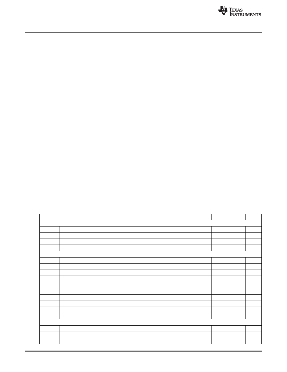
TPS53125EVM-599 Electrical Performance Specifications
Table 1. TPS53125EVM-599 Electrical and Performance Specifications
Parameter
Notes and Conditions
Min
Typ
Max
Unit
Input Characteristics
V
IN
Input Voltage
8
12
22
V
I
IN
Input Current
V
IN
= 12 V, I
OUT1
= 4 A, I
OUT2
= 4 A
–
1.2
1.5
A
No Load Input Current
V
IN
= 12 V, I
OUT
= 0 A
–
20
35
mA
V
IN_UVLO
Input UVLO
I
OUT
= 4
4.0
4.2
4.5
V
Output Characteristics
V
OUT1
Output Voltage 1
V
IN
= 12 V, I
OUT
= 2 A
1.03
1.05
1.07
V
Line Regulation
V
IN
= 8 to 22
–
–
1%
Load Regulation
I
OUT
= 0 A to 4 A
–
–
1%
V
OUT1_rip
Output Voltage Ripple
V
IN
= 12 V, I
OUT
= 4 A
–
–
30
mVpp
I
OUT1
Output Current 1
V
IN
= 8 V to 22 V
0
4
A
V
OUT2
Output Voltage 2
V
IN
= 12 V, I
OUT
= 2 A
1.78
1.80
1.82
V
Line Regulation
V
IN
= 8 V to 22 V
–
–
1%
Load Regulation
I
OUT
= 0 A to 4 A
–
–
1%
V
OUT2_rip
Output Voltage Ripple
V
IN
= 12 V, I
OUT2
= 4 A
–
–
30
mVpp
I
OUT2
Output Current 2
V
IN
= 8 V to 22 V
0
4
A
Systems Characteristics
F
SW
Switching Frequency
200
350
400
kHz
h
pk
Peak Efficiency
V
IN
=12
–
88%
–
h
Full Load Efficiency
V
IN
= 12, I
OUT1
= I
OUT2
= 4 A
–
80%
–
2
TPS53125EVM-599
SLVU392 – July 2010
Copyright © 2010, Texas Instruments Incorporated