Chapter 2. hardware installation, 1 the front panel, 2 the back panel – TP-Link TD-8817B User Manual
Page 9: Chapter 2, Hardware installation, The front panel, The back panel
TD-8817B
ADSL2/2+ Ethernet/USB Router User Guide
3
Chapter 2. Hardware Installation
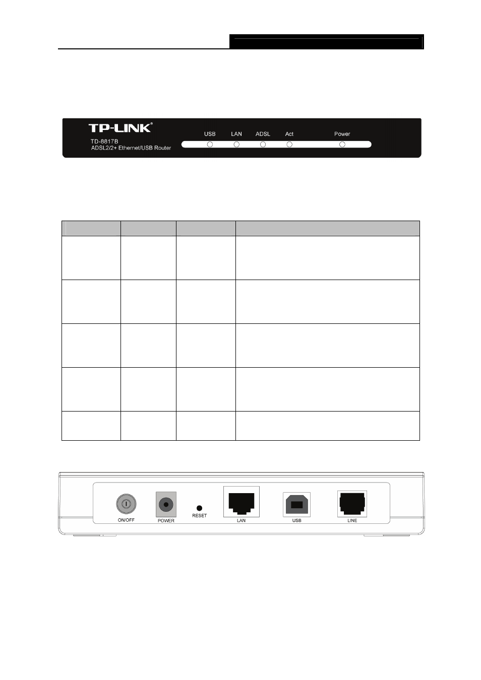
2.1 The Front Panel
Figure 2-1
The LEDs are located on the front panel, they indicate the device’s working status. For details,
please refer to LED Explanation.
LED Explanation:
Indicator
Description
Status
Function Details
USB USB
status
On
Off
Flash
Connection to telecom network is OK
Connection on USB port is abnormal
Data is transmitting or receiving
LAN Ethernet
On
Off
Flash
Connection to telecom network is OK
Connection on LAN port abnormal
Data is transmitting or receiving
ADSL
ADSL
status
Slow flash
Quick flash
On
Connection to telecom network is abnormal
Connecting to the telecom network
Connection to telecom network is OK
Act Data
Flash
Off
There is data transmitting or receiving on WAN
port
No data transmitting or receiving on WAN port
Power Power
On
Off
Power OK
Power fail
2.2 The Back Panel
Figure 2-2
¾
On/OFF: The switch for the power.
¾
POWER: The Power plug is where you will connect the power adapter.
¾
RESET: There are two ways to reset the Router's factory defaults.
Method one: When the device is working, please press the reset button of the Router, keep
the reset button pressed down for more than five seconds.