4 stand-alone connection diagrams – Texas Instruments TPA0243 User Manual
Page 15
2-5
2.4
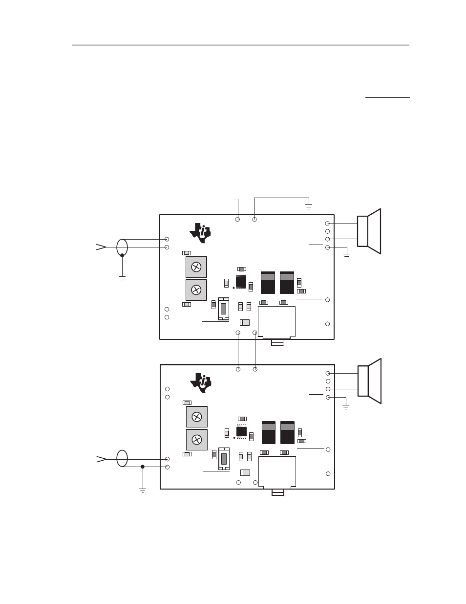
Stand-Alone Connection Diagrams
The power supply range is 2.5 V to 5.5 V and isolated RO/MO+ and LO/MO–
lines for BTL operation are required.
Note that the source of any shutdown signal applied to the EVM SHUTDOWN
pin must be able to sink the current flowing through the pullup resistor on the
module (100 k
Ω
) when the pin is held low.
2.4.1
TPA0243 EVMs Connected for Stereo BTL Output
Figure 2–3 shows two TPA0243 EVMs connected for stereo BTL operation.
Figure 2–3. TPA0243 EVMs Connected for Stereo BTL Output
GND
LO/MO+
SHUTDOWN
GND
C3
VDD
GND
GND
LIN
VDD
GND
GND
RIN
TPA0243 EVM Board
U1
+
TEXAS
INSTRUMENTS
2000
R2
S1
R1
STEREO/MONO
C4
C5
R4
C6
C1
C2
J1
R3
R5
SLOP269
SHUTDOWN
R9
R6
C8
C7
R8
R7
+
RO/MO+
GND
LO/MO+
SHUTDOWN
GND
C3
VDD
GND
GND
LIN
VDD
GND
GND
RIN
TPA0243 EVM Board
U1
+
TEXAS
INSTRUMENTS
2000
R2
S1
R1
STEREO/MONO
C4
C5
R4
C6
C1
C2
J1
R3
R5
SLOP269
SHUTDOWN
R9
R6
C8
C7
R8
R7
+
RO/MO+
Right
Left
5 VDC
Audio
Input
(Left)
Audio
Input
(Right)
5 VDC
GND