Unpacking, Contents of hardware pack – Troy-Bilt T-106 User Manual
Page 8
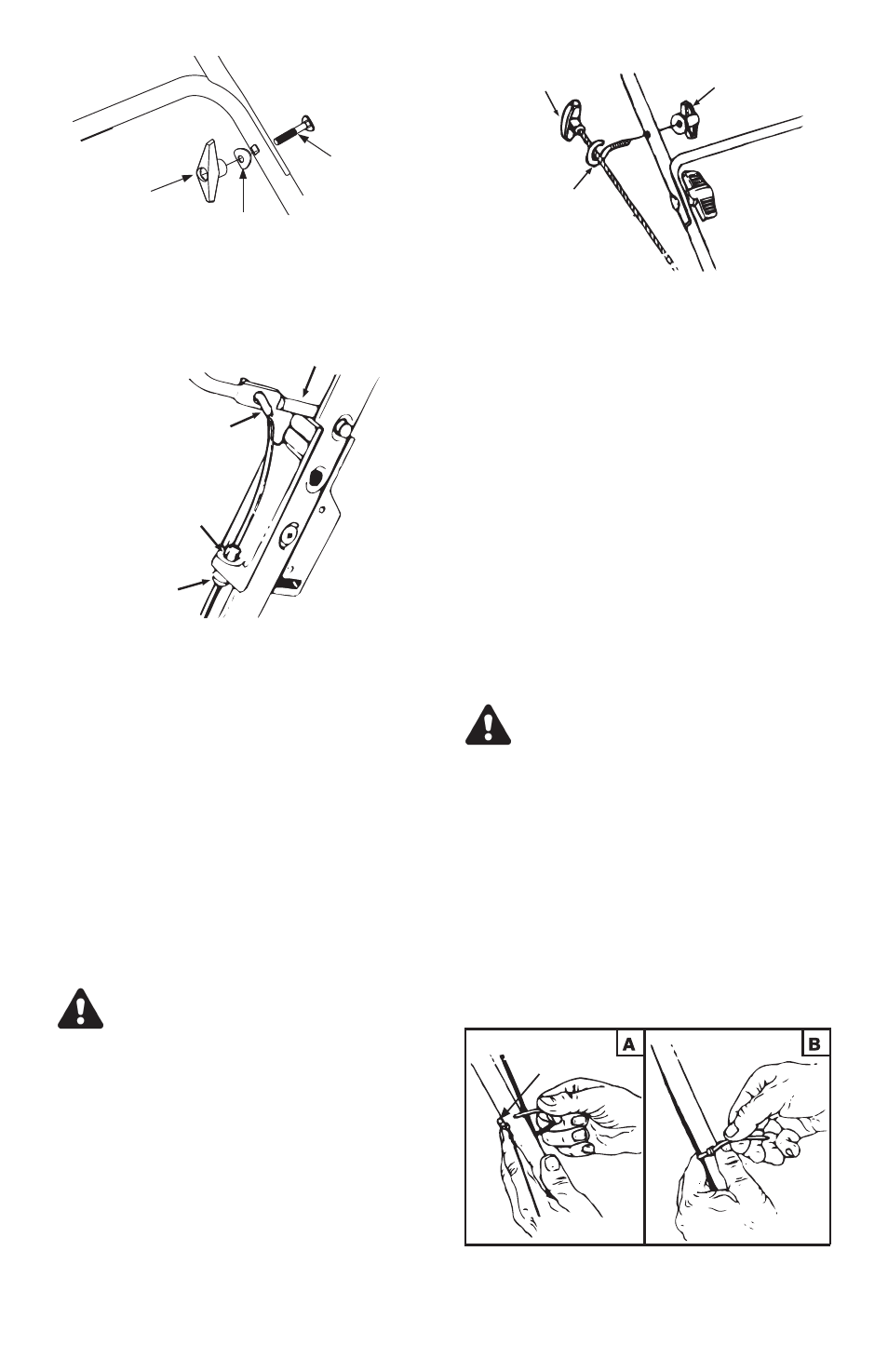
ATTACHING THE BLADE CONTROL
CABLE
• The brake cable is attached to the engine,
and has a “Z” fitting on the loose end. Route
the brake cable over the lower handle. Place
end of cable through the hole in the control
box as shown in figure 3. Push the plastic
fitting until it locks into the hole in the throt-
tle box.
• Move the blade control handle away from
the upper handle. Hook the “Z” end of the
brake cable into the hole in the blade con-
trol handle from the outside to the inside as
shown in figure 3.
WARNING: Brake cable must be as-
sembled as shown for proper blade
brake operation.
ATTACHING THE STARTER ROPE
(Hardware C)
• The starter rope is inside the top of the en-
gine. Additional rope may be wound around
the starter handle. If so, unwind the rope
from the handle.
• With the spark plug wire disconnected and
grounded, depress the blade control handle
and pull the rope out of the engine.
• Place the rope guide around the starter han-
dle, so the opening in the rope guide is
toward the front of the mower as shown. In-
sert the rope guide into the right side of the
handle.
• Secure with small wing nut. See figure 4.
NOTE: If the starter rope becomes dis-
connected from rope guide on handle,
disconnect and ground the spark
plug wire. Depress the blade control
handle and pull the starter rope out
from engine slowly. Slip the starter
rope into the rope guide bolt on han-
dle.
SECURING THE CABLES (Hardware D)
Secure the cable to the left side of the han-
dle as follows:
WARNING: When attaching the con-
trol cables, the cables must be
routed to avoid contact with all
sharp edges and hot surfaces to
prevent damage to the cables,
which will render the control inoper-
ative.
• Insert posts on cable ties into holes pro-
vided on the handle, one on the upper
handle and one on the lower handle. The
holes may be either on the inside or outside
of the handles. See figure 5A.
• Secure the cables with the cable ties. See
figure 5B. Trim excess ends of cable ties.
8
Figure 3
Hole in
bracket
Plastic Fitting
"Z" Fitting
Blade Control Handle
Figure 4
Rope Guide
Small Wing
Nut
Starter Handle
Figure 2
Large
Wing Nut
Carriage
Bolt
Saddle
Washer
Figure 5
Post on
Cable Tie