Pa g e 1 5 /2 2, Tandberg – TANDBERG Telepresence T3 119076.02 User Manual
Page 15
P
A
G
E
1
5
/2
2
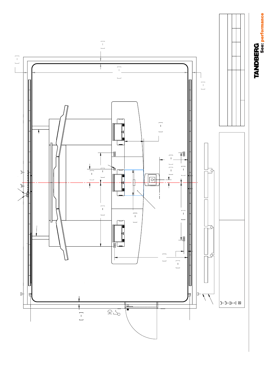
119076.02 TELEPRESENCE T3 ROOM REQUIREMENTS 12.08
140 5
1 2
"
140 5
1 2
"
4600 181
1 8
"
85 3
3 8
"
85 3
3 8
"
111 4
3 8
"
1695 66
3 4
"
885 34
7 8
"
400 15
3 4
"
885 34
7 8
"
1885 74
1 4
"
2160 85"
570 22
1 2
"
760 29
7 8
"
829 32
5 8
"
87,5 3
3 8
"
Centerline
4 single power outlets
5 single power outlets
Hardwire outlet - Light
Lan outlet
110V/30A, 220V/16A
110V/30A, 220V/16A
110V/30A, 220V/16A
On Floor Cable Routing - Transport cables from T3 Power / AV / Lan
Video Lan
Customers Lan
Master Panel Light
Control Data Panel
Doc Cam Outlet
Doc Cam Capture Area Max. size 760 x 570 Min. size 50 x 45
On floor Cable Routing - Transport cables from T3
Unit: mm/"
Scale:
Sheet Size:
Drw No.
:
TANDBERG
T3 Electrical System
04.11.08
01
119083
www.tandberg.com
Doc Cam location in suspended ceiling
110V/30A, 220V/16A
Ceiling hardwire outlet - Light
Fuse - Power outlets: A,B,C,D
Doc Cam, Ceiling lights and LED module : Fuse D
17.11.08
02
All Hardwire outlets : Fuse D
4
01.12.08
03
A A A B C
A A B C
Hardwire outlet for light, mounted sideways on wood lattice.
Hardwire outlet for light, mounted sideways on wood lattice.
LED 5
LED 4
LED 3
LED 2
LED 1
3 x junction box
Leader Cable
LED prganisation Europe (Junction box and extrs cables supplied by local electrician
5
4
Leader Cable
Doc. Title:
Sign.:
Date:
Revision:
Related Tandberg Product -
TANDBERG T3
1:25
A3
Fire Emergency switch
(Controls fuse groups A,B and C)
5
Note that the fire
emergency switch is a
control switch only
. The
actual switching should
take place in the power
cabinet itself.
A sign informing about the
Fire emrgency switch should
be put on the inside wall next
to the door
. For more on the
sign see page 12.