Iwsa 500, Input level attenuator, Crossover frequency adjustment – Tannoy iwSA 500 User Manual
Page 5: Phase control, Crossover / bypass switch, On/auto switch
5
TANNOY iwSA 500
iwSA
500
4 . 0 I N T R O D U C T I O N
4 . 1 U n p a c k i n g
Thank you for purchasing a Tannoy power amplifier. This manual contains important information on operating your amplifier correctly and safely.
Please take some time and read this manual to familiarize yourself with the advanced features of this amplifier.
Carefully open the shipping carton and check for any noticeable damage. Every Tannoy amplifier is tested and inspected before leaving the factory
and should arrive in perfect condition. If found to be damaged, notify the shipping company immediately. Only the consignee may institute a claim
with the carrier for damage incurred during shipping. Be sure to save the carton and packing materials for the carriers inspection.
It is also advisable to save the carton and packing material, even if the amplifier is undamaged. Should you ever need to ship the amplifier, always
use original packaging.
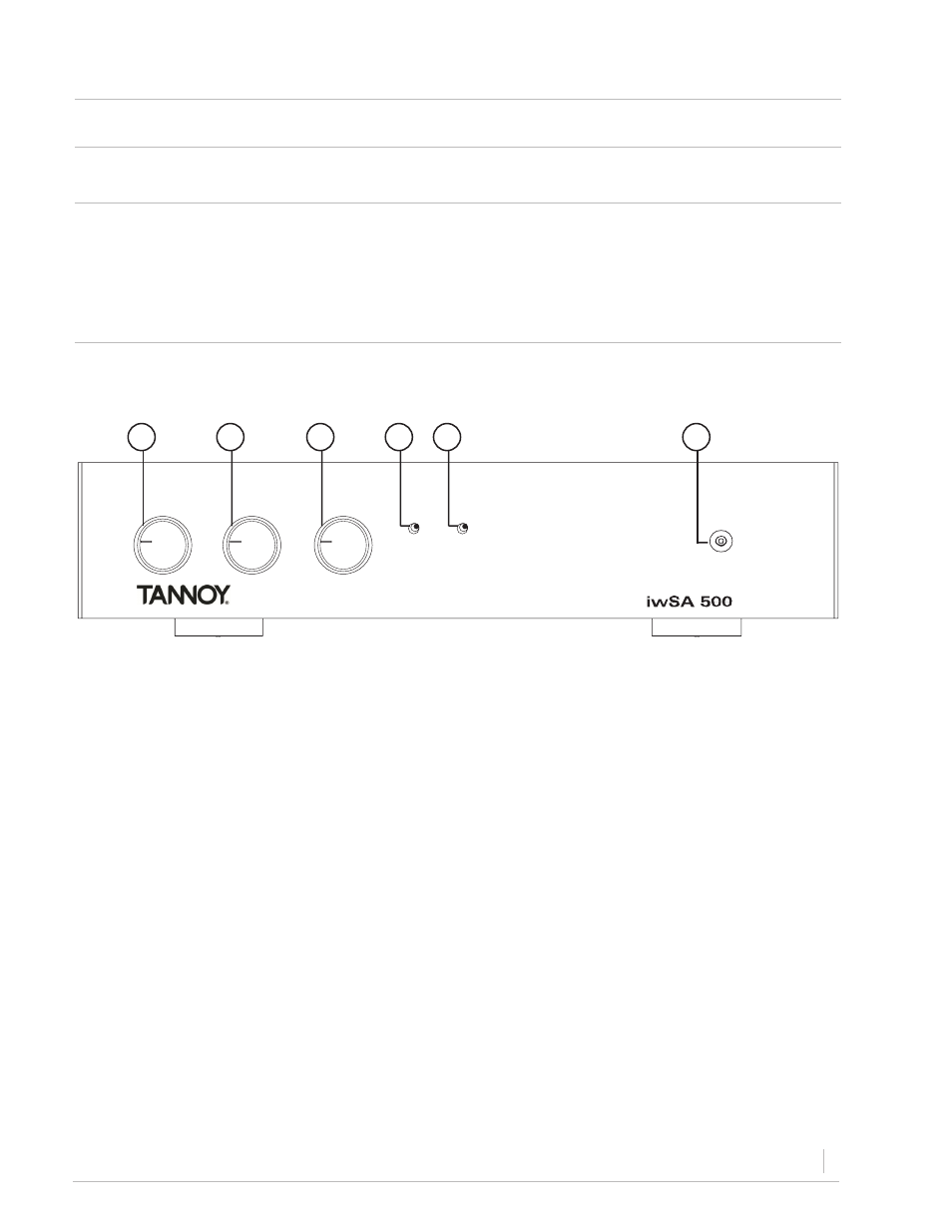
4 . 2 F r o n t P a n e l
This control is used to alter the signal level entering the amplifier or to cut down the unwanted noise from the input signal.
PHASE
POWER
CROSSOVER
ON
AUTO
CROSSOVER
FREQUENCY
LEVEL
BYPASS
50
150
0
180
1. Input level attenuator
Continuously variable from 50Hz - 150Hz, to allow custom integration with various mid/high units and installation positions.
2. Crossover frequency adjustment
Continuously variable from 0° - 180° to allow custom integration with mid/high units in various installation positions.
3. Phase control
Allows the low pass crossover to be taken out of the circuit so an external crossover can be used.
4. Crossover / Bypass switch
In the auto position the amplifier will go into sleep mode when there is no signal present for 20-30
minutes. On position defeats the sleep mode.
5. On/Auto switch
This blue LED indicates that there is power present at the amp and that the rear mounted power switch is on.
6. Power indicator
1
2
3
4
5
6
Figure 1: Front Panel