Lf-3 – QSC Audio DCA Series User Manual
Page 9
9
LF-3
Setting Up the LF-3
LF-3 Factory-installed SIPs
LF-3 Factory Switch Settings
LF-3 Recommended Amplifier Settings
f
xo
350 Hz, both channels (18
k
Ω
SIP resistor installed in J6 and J8)
Delay 1.4 milliseconds, both channels (22
k
Ω
SIP resistor installed in J1 and J2)
Switch 1 and Switch 10 ON:
Delay active (both channels)
Switch 2 and Switches 4 through 9 OFF: Required default setting for proper operation of the LF-3
Switch 3 ON:
Required default setting for proper operation of the LF-3
Clip limiters: ON, (both channels)
Low-frequency filters: ON (both channels), select either 30 or 50 Hertz roll-off depending on speaker specifications (both channels)
Operating mode: Typically Stereo mode, but Parallel mode can be used in applications requiring dual LF amp channels with one source
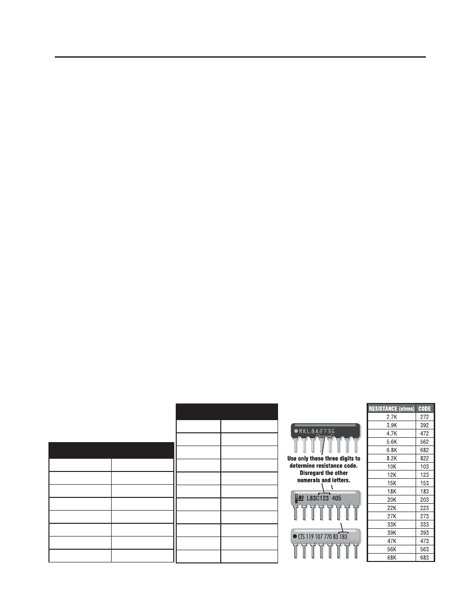
Use these tables to determine the
correct resistor values for the crossover
frequencies and delays you need.
f
(
.
q
e
r
f
r
e
v
o
s
s
o
r
C
O
X
)
e
u
l
a
v
r
o
t
s
i
s
e
r
P
I
S
z
H
0
8
K
8
6
z
H
0
5
1
K
9
3
z
H
0
0
2
K
7
2
z
H
0
5
2
K
2
2
z
H
0
0
3
K
0
2
z
H
0
5
3
K
8
1
z
H
0
0
4
K
5
1
z
H
0
0
5
K
2
1
Identifying SIP resistor networks
When shipped from the factory, the DIP switch settings should be set as follows:
)
s
m
(
y
a
l
e
D
e
u
l
a
v
r
o
t
s
i
s
e
r
P
I
S
8
.
1
K
7
2
4
.
1
K
2
2
3
.
1
K
0
2
2
.
1
K
8
1
1
K
5
1
8
.
0
K
2
1
7
.
0
K
0
1
6
.
0
K
2
.
8
5
.
0
K
8
.
6
4
.
0
K
6
.
5
3
.
0
K
7
.
4