3 vent system diagram, 2 installation of make-up combustion air, Notice – Quincy Compressor Air Compressor User Manual
Page 12: Dvh-5
For DVH kits:
4. Use 4 inch diameter flex pipe that is provided in the kit or a comparable single wall metal pipe. The
maximum allowable length of intake pipe is ten feet not including elbows.
5. Begin installing the 4” tee to the burner (Riello and Heat Wise require the supplied 3” to 4” increaser to be
installed first). Secure all joints on the intake with three screws each.
6. Install the supplied vacuum relief damper in the branch of the tee making sure that it is mounted with all
labeling right side up and perfectly horizontal.
7. Off of the last leg of the tee install the 4” duct elbow, and then the aluminum flex pipe.
8. Finally attach the other end of the flex pipe to the intake hood or intake port on the concentric hood.
9. Inspect the intake system and make sure all connections are secure and then seal each joint with silicone or
aluminum tape.
2.2 Installation of Make-up Combustion Air
NOTICE
Do not operate the burner with air intake disconnected.
9
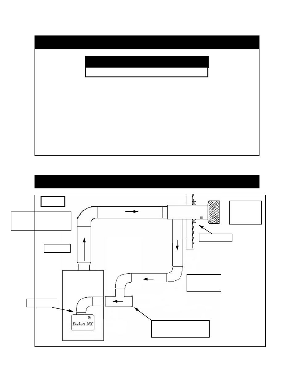
Vent Connector
Must Be Sealed Design
Air Boot
Exhaust
Combustion
Air
Positive
Pressure
Oil Fired
2.3 Vent System Diagram
DVH-5
2” X 2” Frame
Direct Vent
System
Terminal
Vacuum Relief Valve
(w/ RC-4 Damper)