Omega FMA 1500 User Manual
Page 8
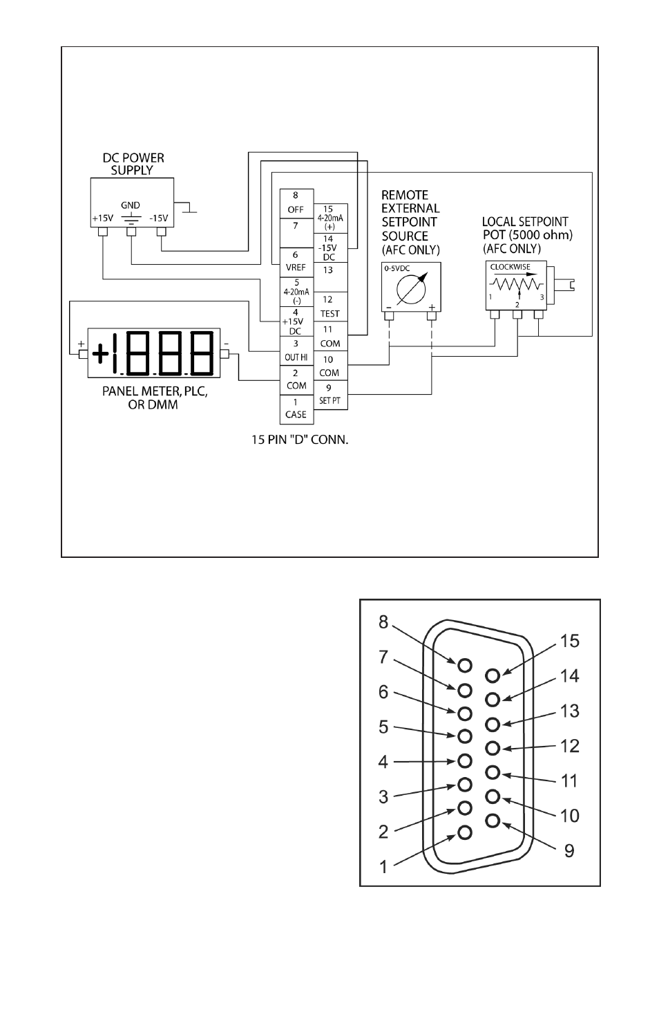
FIGURE 2-1, WIRING DIAGRAM FOR FMA 1400/1500 TRANSDUCERS
FIGURE 2-3, FMA 1400/1500 15 PIN "D" CONNECTOR CONFIGURATION
3
PIN FUNCTION
1
Chassis Ground
2
Common, Signal Ground For Pin 3
3
0-5 VDC Flow Signal
4
+15 VDC Power Supply
5
(-) 4-20 mA Flow Signal (optional)
6
+7 VDC for Local Set Point
7
(unassigned)
8
TTL Valve Off Control (FMA 1400)
9
Control Set Point Input 0 5 VDC (FMA 1400)
10
Common, Signal Ground for Pin 9
11
Common, Power Supply
12
Valve Test Point/Purge (FMA 1400)
13
(unassigned)
14
-15 VDC Power Supply
15
(+) 4-20 mA Flow Signal (optional)
This manual is related to the following products: