Power up and basic parameter setup, Start up procedure, En-15 – Omron Healthcare VARISPEEDF7 User Manual
Page 16
EN-15
Power Up and Basic Parameter Setup
Start Up Procedure
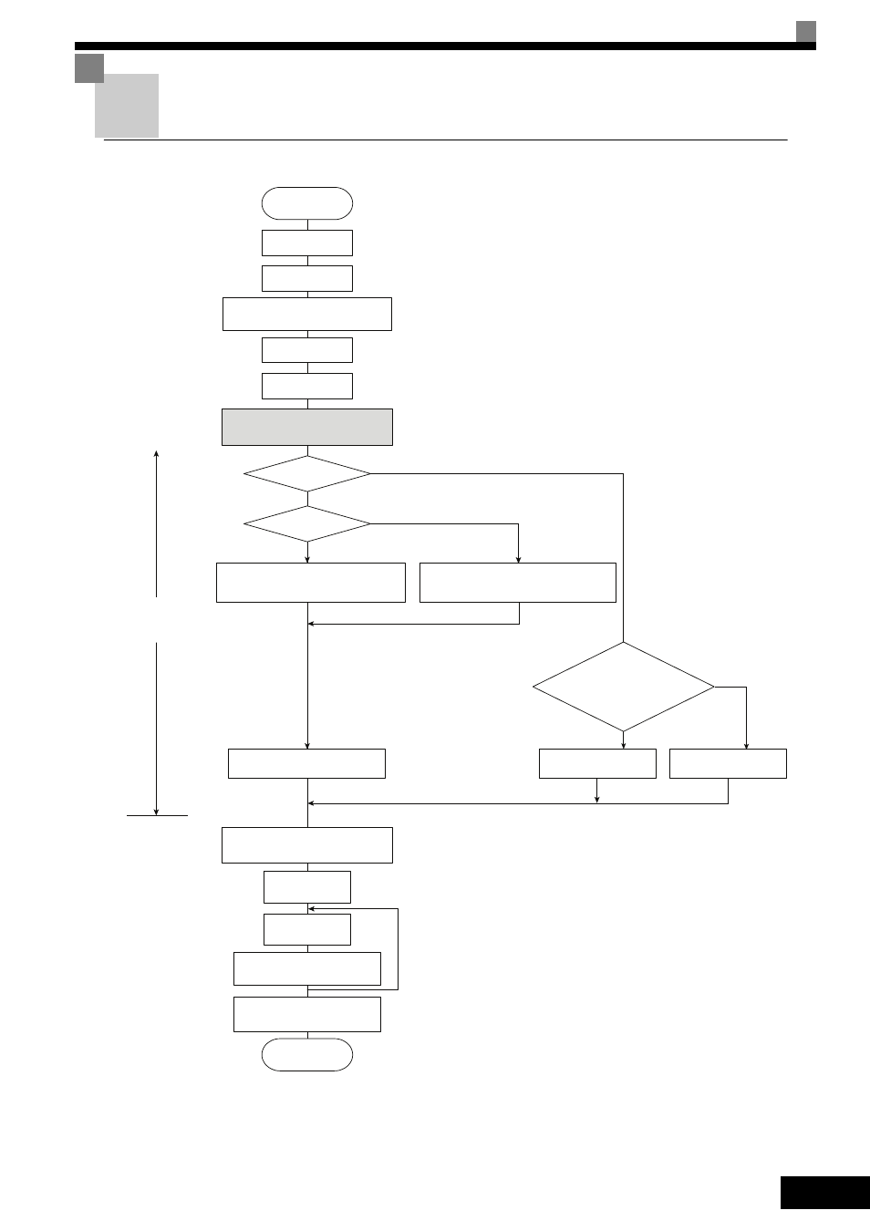
Fig 8 Trial Operation Flowchart
YE
S
*
6
*
6
*
4
Motor
oper
a
tion po
ss
i
b
le
d
u
ring
au
tot
u
ning?
*3
S
etting
s
a
ccording
to control mode
S
TART
In
s
t
a
ll
a
tion
Wiring
S
et power
su
pply
volt
a
ge j
u
mper
*
1
Confirm
s
t
a
t
us
T
u
rn ON power
B
as
ic
s
etting
s
(Q
u
ick progr
a
mming mode)
S
elect control
method.
V/f control
NO
NO
V/f control
YE
S
YE
S
Vector Control (A1-02 = 2 or
3
)
*
5
V/f Control with PG (A1-02 = 1
S
et E1-0
3
.
V/f def
au
lt: 200V/50Hz (400V/50Hz)
S
et E1-0
3
, E2-04
a
nd F1-01.
*
2
V/f def
au
lt: 200V/50Hz (400V/50Hz)
Rot
a
ting
au
tot
u
ning
Non-rot
a
ting
au
tot
u
ning
Non-rot
a
ting
au
tot
u
ning
for line-to-line re
s
i
s
t
a
nce
Applic
a
tion
s
etting
s
(Adv
a
nced progr
a
mming mode)
No-lo
a
d
oper
a
tion
Lo
a
ded
oper
a
tion
Optim
u
m
a
dj
us
tment
s
a
nd p
a
r
a
meter
s
etting
s
Check/record
p
a
r
a
meter
s
etting
s
PG?
END
NO
1. Set for 400 V Class Inverter for 75 kW or more.
2. If there is a reduction gear between the motor and PG, set the
reduction ratio in F1-12 and F1-13 in advanced programming
mode.
3. Use rotational autotuning to increase autotuning accuracy
whenever it is okay for the motor to be operated.
4. If the motor cable changes to 50 m or longer for the actual
installation, perform non-rotating autotuning for the line-to-line
resistance only on site.
5. The default control mode is Open Loop Vector control
(A1-02=2).
6. If the maximum output frequency and the base frequency are
different, set the maximum output frequency (E1-04) after
autotuning.