2 thermocouple, Figure 2.5 thermocouple wiring hookup, Table 2.4 tc wire color chart – Omega CNI16 User Manual
Page 12
2.3.2 Thermocouple
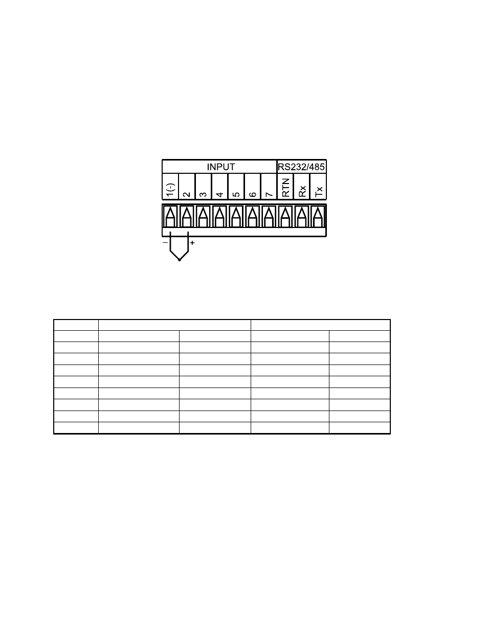
The figure below shows the wiring hookup for any thermocouple type. For
example, for Type K hookup, connect the yellow wire to the "2" terminal and the
red wire to the "1(-)" terminal.
When configuring your controller, select Thermocouple and Thermocouple
Type in the Input Type menu (see Part 3).
Figure 2.5 Thermocouple Wiring Hookup
8
TYPEInput Connector
Jacket (external insulation)
Terminal 1 (-)
Terminal 2 (+)
Extension
Grade
J
Red
White
dark-Brown
Black
K
Red
Yellow
dark-Brown
Yellow
T
Red
Blue
dark-Brown
Blue
E
Red
Purple
dark-Brown
Purple
N
Red
Orange
dark-Brown
Brown
R
Red
Black
-
Green
S
Red
Black
-
Green
B
Red
Gray
-
Black
Table 2.4 TC Wire Color Chart