3 installation, 1 general piping – Omega FTB500 User Manual
Page 6
- 4 -
3 Installation
Upon receipt of the flowmeter carefully inspected it, checking for
any indications of damage which may have occurred during
shipment. Inspect all packing material carefully for parts or
components which may have been packed with the shipment.
Refer to the packing list/invoice for a detailed list of items
included in the shipment.
3.1
General Piping
The Omega FTB500 Series of Low Flowrate Meters is capable of
sensing fluid flow in one direction only. The meter housing is
marked by a flow direction arrow to indicate the direction of flow
through the meter. The meter must be installed in the piping in the
correct orientation to ensure the most accurate and reliable
operation. Care should be taken in the proper selection of the
mating fittings. Size, type of material, and pressure rating should
be the same as the flowmeter supplied.
When it is expected that flow will be intermittent, the meter should
not be mounted at a low point in the piping system. Solids which
settle or congeal in the meter may affect meter performance.
In order to achieve optimum electrical signal output from the
flowmeter, due consideration must be given to its isolation from
ambient electrical interference such as nearby motors, trans-
formers, and solenoids.
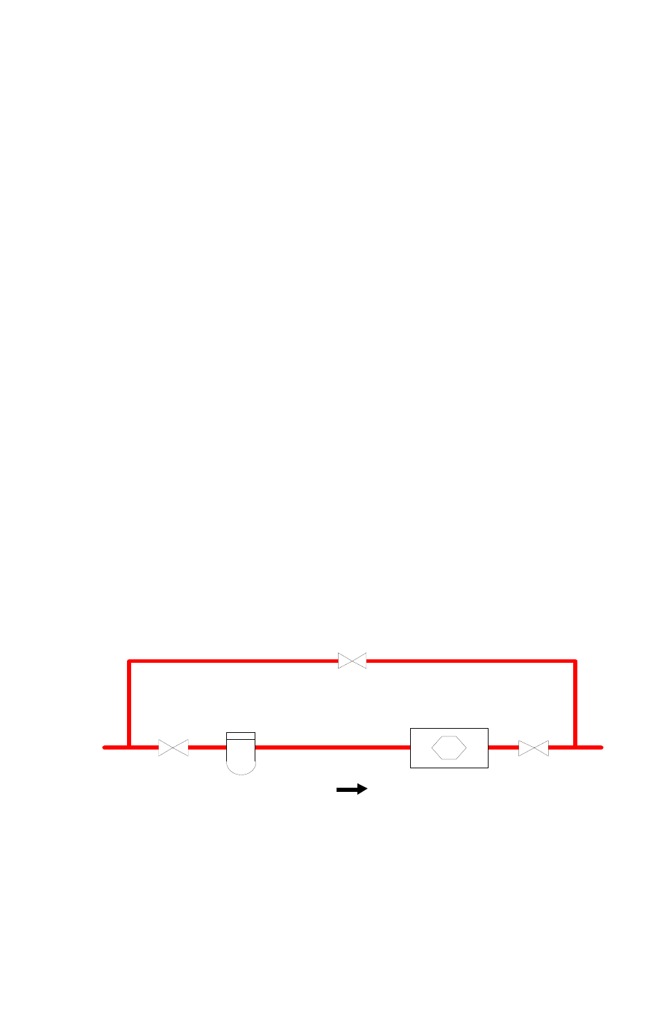
A typical flowmeter installation is shown below:
Blocking and Bypass valves should be installed if it is necessary to
do preventive maintenance on the flowmeter without shutting
down the flow system. The Bypass valve can be opened before the
Blocking valves are closed allowing the flow to continue while
removing the turbine flowmeter for service.
BYPASS RUN
Blocking Valve
Bypass Valve
Blocking Valve
Turbine Flowmeter
METER RUN
Strainer