Ix. single and three phase wire diagram – Oneida Air Systems 5 & 7.5 HP Direct Drive Cyclonic Dust Collectors User Manual
Page 12
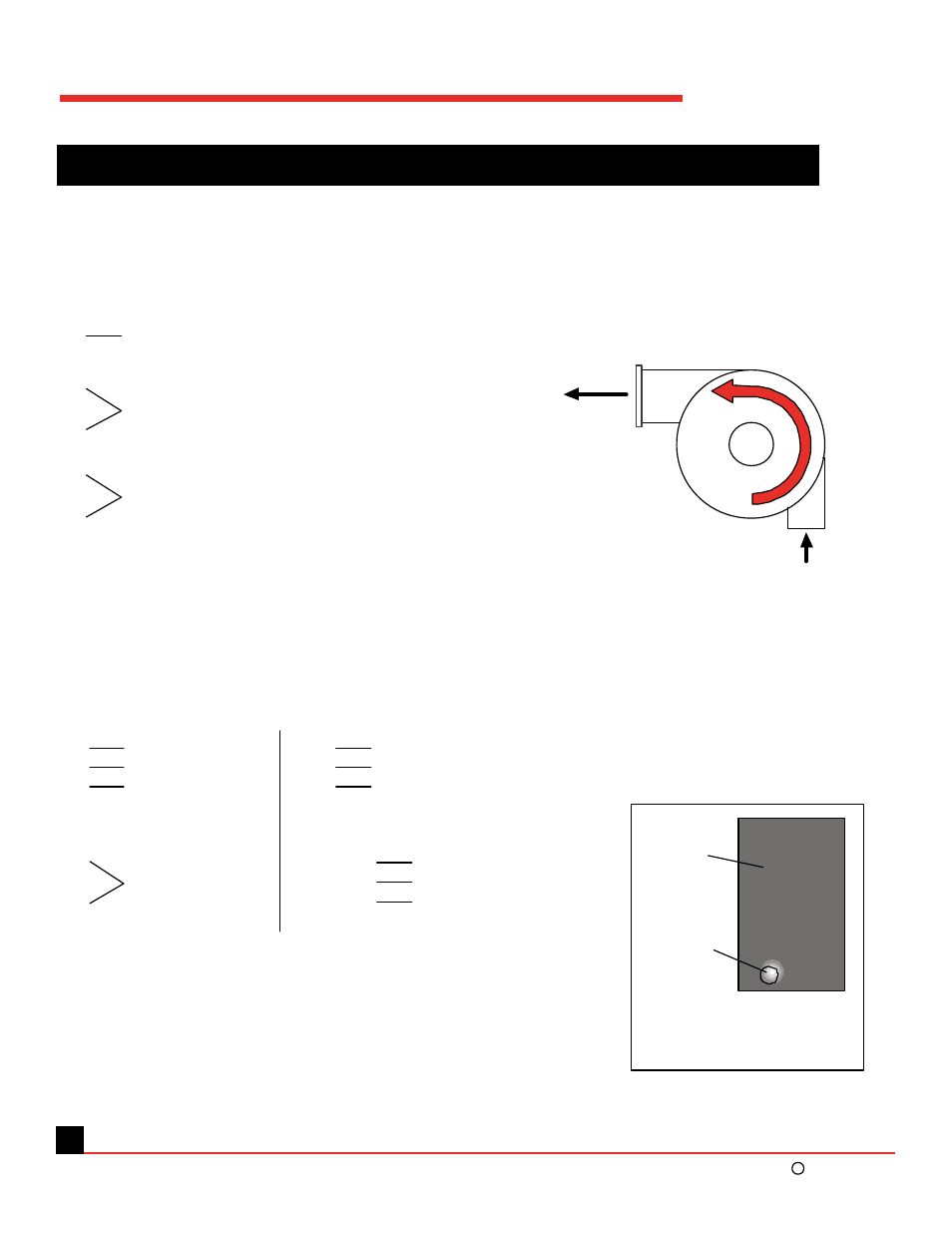
IX. Single and Three Phase Wire Diagram
Use wiring diagram on motor plate if different from below.
- Electrically insulate all connections.
- For counter-clockwise rotation, looking from top of motor down.
5hp Single Phase
Leeson Motor / 230v / 19.8 amps / TEFC / C Face / 3500 rpm
7.5hp Three Phase
Leeson Motor / 208 - 230/460v / 19.6 - 18.4/9.2 amps / TEFC / C Face
/ 3480 rpm
L1
L2
L3
T4
T5
T6
Tie together
Wiring should always be done by a licensed electrician!
Ground: Connect house ground
wire to green chassis screw in
motor wire housing box.
Motor
Wire
Box
Green
Chassis
Screw
11
Top View
Outlet
Inlet
O.A.S. 2002
c
5 - 7.5 HP Direct Drive Owner’s Manual
T1
T8
T4
T5
Tie together and insulate with
a wire nut (do NOT connect to
any house wiring)
Power Line 2*
P1
Power Line 1*
* Power Line 1 and 2 are interchangeable
208 / 230 Volts
T1 & T7
T2 & T8
T3 & T9
L1
L2
L3
T7 & T4
T8 & T5
T9 & T6
Tie together
460 Volts
T1
T2
T3
Tie together
Tie together
To Line to reverse rotation interchange any two line leads
Check rotation after wiring.
Wire for counter-clockwise rotation.