General description, Safety summary, Dimensions in inches (mm) – Omega Vehicle Security DP63000A-I User Manual
Page 3
3
z
FOUR SELECTABLE D.C. RANGES
200
µA, 2 mA, 20 mA, 200 mA
z
MINIMUM AND MAXIMUM DISPLAY CAPTURE
z
LCD, REFLECTIVE OR RED/GREEN LED BACKLIGHTING
z
0.48" (12.2 mm) HIGH DIGITS
z
OPTIONAL SETPOINT OUTPUT MODULES
z
OPTIONAL SERIAL COMMUNICATIONS MODULES (RS232 or RS485)
z
OPERATES FROM 9 TO 28 VDC POWER SOURCE
z
FRONT PANEL OR SOFTWARE PROGRAMMABLE
z
DISPLAY COLOR CHANGE CAPABILITY AT SETPOINT OUTPUT
z
NEMA 4X/IP65 SEALED FRONT BEZEL
GENERAL DESCRIPTION
The DP63000 provides the user the ultimate in flexibility, from its complete
user programming to the optional setpoint control and communication
capability. This unit accepts a DC Current input signal and provides a display in
the desired unit of measure. The meter also features minimum and maximum
display capture, display offset, units indicator, and programmable user input.
The display can be toggled either manually or automatically between the
selected displays.
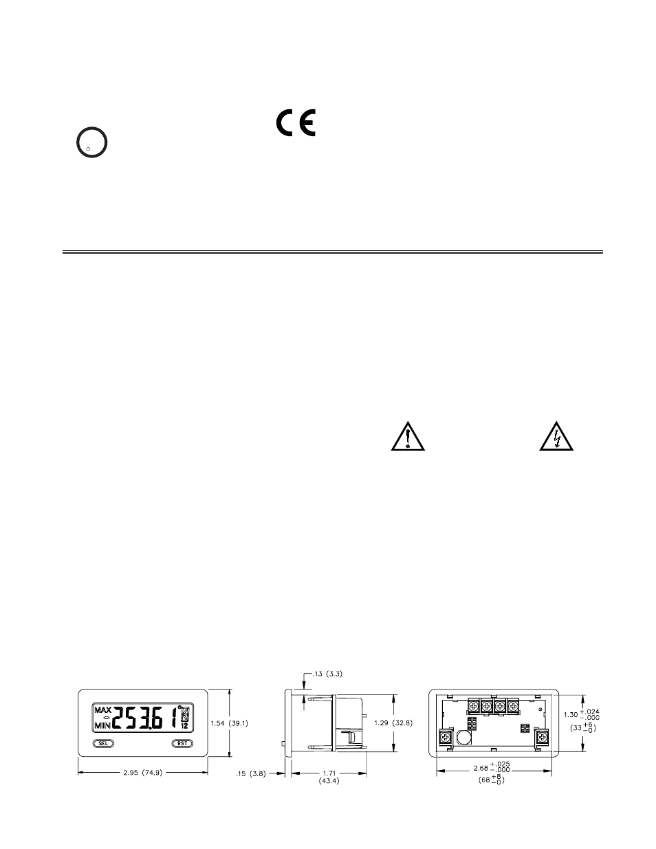
The DP63000 display has 0.48" (12.2 mm) high digits. The LCD is available
in two versions, reflective and red/green backlight. The backlight version is user
selectable for the desired color and also has variable display intensity.
The capability of the DP63000 can be easily expanded with the addition of
option modules. Setpoint capability is field installable with the addition of the
setpoint output modules. Serial communications capability for RS232 or RS485
is added with a serial option module.
The DP63000 can be powered from an optional Power Supply (Model
Number DP6-MLPS1), that attaches directly to the back of a DP63000. The
DP6-MLPS1 is powered from 85 to 250 VAC and provides up to 400 mA to
drive the unit and sensors.
CURRENT
This unit is the DC Current meter. It features 4 current input ranges, that are
selected by the user via a programming jumper and software input range
selection. The ranges consist of following: 200
µA, 2 mA, 20 mA, or 200 mA.
Users should select the appropriate current range that covers their maximum
signal input.
SAFETY SUMMARY
All safety related regulations, local codes and instructions that appear in this
literature or on equipment must be observed to ensure personal safety and to
prevent damage to either the instrument or equipment connected to it. If
equipment is used in a manner not specified by the manufacturer, the protection
provided by the equipment may be impaired.
Do not use this meter to directly command motors, valves, or other actuators
not equipped with safeguards. To do so can be potentially harmful to persons or
equipment in the event of a fault to the meter.
CAUTION: Risk of Danger.
Read complete instructions prior to
installationand operation of the unit.
CAUTION: Risk of electric shock.
DIMENSIONS In inches (mm)
Note: Recommended minimum clearance (behind the panel) for mounting clip installation is 2.15" (54.6) H x 3.00" (76.2) W.
C
US LISTED
US LISTED
UL
4
IND. CONT. EQ.
51EB