The removal connector, Wiring diagrams – RBH Sound MC-615-70 User Manual
Page 5
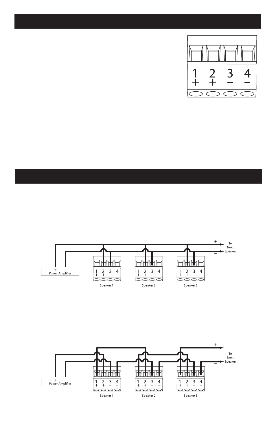
The Removal Connector
This connector detaches from the main housing of the
speaker for ease in connecting the speaker wire. The
bare wire must be inserted and securely fastened by
tightening the screws. The connector has 4 terminals as
shown in the diagram below.
Positions 2 and 3 are inputs from either the amplifier
or a previous speaker. They are the same inputs used
for 8 Ohm operation. Positions 1 and 4 are outputs to
succeeding speakers in 70 volt operation. We suggest carefully reading the Wiring
Diagrams section of this manual to determine the best wiring scheme for your
particular installation.
This removable connector will accept a maximum wire gauge of 14 AWG and a
minimum wire gauge of 18 AWG. Please refer to the NEC (National Electrical Code)
for further information regarding the permissible wire size.
Wiring Diagrams
Parallel Connection
Connect the speaker wire going to succeeding speakers to positions 2 and 3 as
shown in the diagram below. If needing to service system, this will allow the
removable connector to be removed from the speaker with all other speakers in the
line continuing to play and operate normally.
Loop Thru
Positions 1 and 4 are internally connected to positions 2 and 3 as shown in the
below diagram. This allows connections to succeeding speakers using positions 1
and 4. If the system needs, removing the removable connector from one speaker
will cause all succeeding speakers to stop playing.
3