11
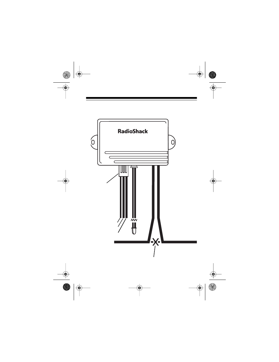
WIRING DIAGRAM
Yellow — Antenna
Black — Ground
Red — +12 Volts
To the
Ignition Switch
To the
Starter Solenoid
R
e
d/
B
la
c
k
— T
o
S
w
itc
h
Wh
ite
—
To
Sta
rt
e
r
St
a
tus
Indi
c
a
tor
Cut the wire going from
the Ignition Switch to the
Starter Solenoid.
Power Harness
49-851.fm Page 11 Thursday, August 19, 1999 10:56 AM