Radio Shack System 350 User Manual
Page 16
16
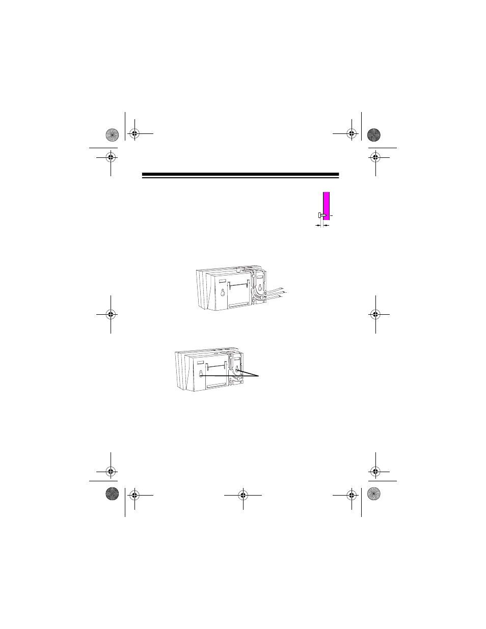
3. Thread a screw through each hole, letting the
head extend
1
/
8
inch from the wall.
4. Attach the mounting bracket to the system
(see “” on Page 15).
5. Route the phone line cords and AC adapter
cord through the slots on the back of the
bracket.
6. Line up the keyhole slots on the bracket with the screws in
the wall, then slide the system down onto the screws until
it is secure.
1
/
8
"
Keyhole Slots
43-991A.fm Page 16 Tuesday, December 28, 1999 7:59 AM
See also other documents in the category Radio Shack Phones:
- 43-1302 (2 pages)
- 4-Line System Speakerphone with Caller ID and Headset Jack (28 pages)
- CLEAR TRIM-FONE 43-858 (2 pages)
- 43-3261 (2 pages)
- ET-182 (2 pages)
- TAD-1024 (24 pages)
- 43-811 (2 pages)
- 43-3909 (4 pages)
- ET-238 (2 pages)
- HandsfreePhone withCallerID/CallWaiting (16 pages)
- 4-Line Telephone System with Speakerphone and Caller ID (28 pages)
- TAD-1018 (24 pages)
- ET-895 (2 pages)
- 43-3228 (8 pages)
- 43-861 (2 pages)
- 43-3201 (4 pages)
- 43-838 (2 pages)
- ET-893 (12 pages)
- ET-208 (2 pages)
- TAD-1028 (28 pages)
- ET-3222 (2 pages)
- Desktop Phone (8 pages)
- ET-898 (2 pages)
- 43-3260 (1 page)
- 43-3910 (4 pages)
- ET-3507 (20 pages)
- TAD-1016 (36 pages)
- TAD-1004 (28 pages)
- 43-3872 (76 pages)
- COUNTRY LIFE 43-860 (16 pages)
- ET-3206 (2 pages)
- ET-899 (2 pages)
- ET-652 (20 pages)
- 1250 (24 pages)
- ET-3204 (2 pages)
- ET-651 (8 pages)
- 43-3206 (2 pages)
- ET-501 (2 pages)
- ET-212 (2 pages)
- ET-886 (2 pages)
- ET-177 (2 pages)
- 4LM053Y2 (14 pages)
- TAD-725 (32 pages)
- ET-205 (2 pages)