Assembly – Ryobi DP121L User Manual
Page 15
15
ASSEMBLy
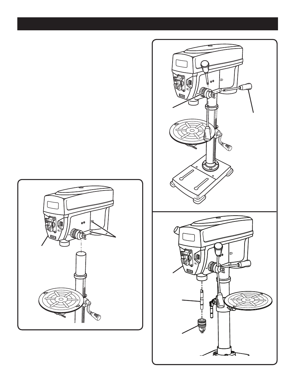
Fig. 11
head
assembly
INSTALLING CHUCK, HEAD ASSEMBLy, AND
FEED HANDLES
See Figures 9 - 11.
NOTE: Move the table out of the way before beginning
installation.
Position the head assembly onto the column with the
chuck positioned over the table.
NOTE: The head assembly is heavy. Get help when
needed.
Slide the head assembly down as far as it will go. Align
the head assembly with the base then tighten the two
head set screws with the hex key.
Attach the three feed handles by screwing them into the
threaded holes in the hub.
Position chuck on spindle. Chuck should be fully opened
to avoid damaging jaws.
Using a piece of scrap wood to protect the chuck, firmly
tap the chuck into place using a mallet or hammer.
Fit the spindle into the spindle shaft turning it to the right
until it slips into place and tap with mallet using a piece
of wood.
set
screws
feed
handle
Fig. 10
Fig. 9
hub
chuck
sPindle
head
assembly
- CS30 RY30020B (26 pages)
- D40 (14 pages)
- HG500 (14 pages)
- HG500 (36 pages)
- HG500 (36 pages)
- R10510 (14 pages)
- HP961 (14 pages)
- SA14402 (20 pages)
- RY30560 (26 pages)
- HP41LK (14 pages)
- EJ101 (20 pages)
- P211 (40 pages)
- P211 (22 pages)
- P310 (16 pages)
- P310 (28 pages)
- P310 (24 pages)
- P520 (18 pages)
- RY26500 (58 pages)
- RY30971 (30 pages)
- RY15518 (30 pages)
- P2500 (16 pages)
- HP36KF (12 pages)
- D130VR (12 pages)
- HP1802M (16 pages)
- P200 (20 pages)
- AG450 (14 pages)
- D550H (16 pages)
- SA960 (20 pages)
- ELL0001 (18 pages)
- BGH825 (18 pages)
- TR30 (14 pages)
- HPL50 (18 pages)
- RY52905 (24 pages)
- RY52604 (52 pages)
- D46CK (16 pages)
- RY961 (14 pages)
- HP61 (14 pages)
- HG300 (14 pages)
- P210 (20 pages)
- D50VSR (12 pages)
- RJ150V-01 (14 pages)
- BGH827 (36 pages)
- BGH616 (18 pages)
- HP62 (18 pages)
- HT230 (22 pages)