Operation – Ryobi RY08570 User Manual
Page 11
11
FILLING THE TANK
WARNING:
Always stop the engine before filling the fuel tank. Never
add fuel to a machine with a running or hot engine. Move
at least 30 ft. from the refueling area before starting engine.
Do not smoke while filling the tank.
n
Clean the surface around the fuel cap to prevent contami-
nation.
n
Loosen the fuel cap slowly, by turning it counter-
clockwise.
n
Pour the fuel mixture carefully into the tank.
n
Clean and inspect the fuel cap gasket before replacing
the fuel cap.
n
Replace the fuel cap and tighten it by turning it clock-
wise.
n
Wipe spilled fuel from the product.
n
Move at least 30 ft. away from refueling area before start-
ing the product.
WARNING:
Check for fuel leaks. If you find any leaks, correct the
problem before using the product.
WARNING:
A leaking fuel cap is a fire hazard and must be replaced
immediately.
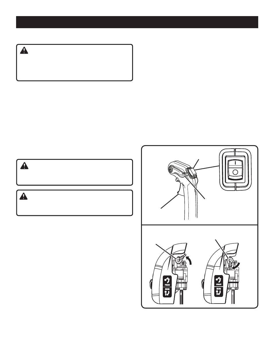
STARTING AND STOPPING
See Figures 6 - 7.
NOTE: It is normal for smoke to be emitted from a new
engine during first use.
To start an engine that is cold or has run dry:
n
Fill the fuel tank, if necessary. Always use the proper
oil/gasoline mixture. See “Mixing the Fuel” on page 10.
n
Disengage the cruise control lever.
NOTE: Do not engage the throttle trigger during the
starting process.
n
Slowly push the primer bulb seven times.
OPERATION
n
Set the choke lever to the
START position.
NOTE: If restarting a warm engine, leave the choke lever
in the
RUN position.
n
Pull the starter cord until the engine runs.
n
Return the starter cord gently to the starter housing. Do
not allow the rope to snap back.
n
Allow the engine to run for 15 seconds to warm up before
using.
n
Engage the throttle trigger to operate.
To stop the Backpack Blower:
n
Release the throttle trigger.
n
Press and hold the engine switch to the “
O” or STOP posi-
tion.
To Remove Backpack Blower:
n
Move harness straps off the shoulders. Let straps slide
down arms.
n
Grasp the straps and lower the blower to the ground.
Fig. 6
THROTTLE
TRIGGER
Fig. 7
ENGINE
SWITCH
CHOKE
LEVER
START
POSITION
RUN
POSITION
CHOKE
LEVER
CRUISE CONTROL
(THROTTLE LOCK)