RTS Digital Matrix Intercom RT-2M User Manual
RTS Hardware
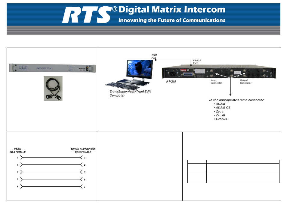
RT-2M (90007891000) Quick Start Guide
NOTE:
See the entire system diagram on reverse side.
RS-232 Cable Pinout
Step 1. Cable the Trunk Supervisor/TrunkEdit PC to the
RT-2M.
NOTE:
In Trunk Supervisor, you must designate
the intercom and port number the RT-2M
sends the test signal over.
To cable the Trunk Supervisor/TrunkEdit PC to the
RT-2M, do the following:
1.
Using the included cable, connect a COM port on
the Trunk Supervisor computer to the RS-232
Interface connector on the rear panel of the RT-2M.
Step 2. Cable the RT-2M to the Frame.
To cable the RT-2M to the Frame, do the following:
1.
Using the appropriate connector defined below, connect the
RT-2M to the Frame:
2.
Connect the other end of the connector to the trunking
connection port as defined in the Trunk Supervisor software.
CONNECTOR
CONNECTION
RJ-12
•
Plug pins 2 and 5 into the Ch 1 input connector terminals.
•
Plug pins 3 and 4 into the Ch 1 output connector terminals.
DB-9
•
Plug pins 7 and 8 into the Ch 1 input connector terminals
•
Plug pins 4 and 5 into the Ch 1output connector terminals.
INCLUDED PARTS:
•
RT-2M Unit
•
DB-9 Cable
LIT000306000 Rev. A
11/2008