Lc c c, Speaker impedance – Rockford Fosgate 401SP User Manual
Page 9
9
I
NSTALLATION
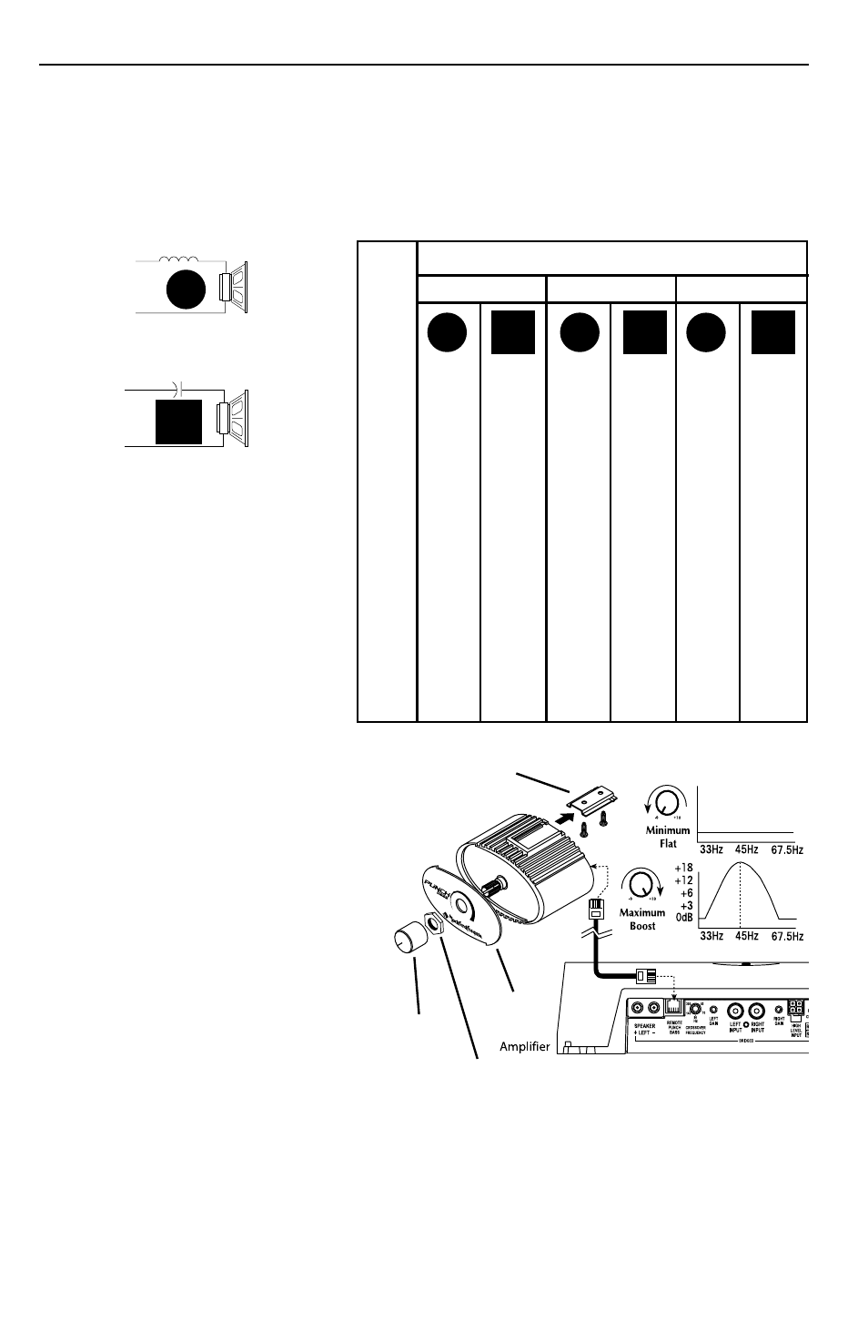
80
4.1mH 1000µF
8.2mH
500µF
16mH
250µF
100
3.1mH
800µF
6.2mH
400µF
12mH
200µF
130
2.4mH
600µF
4.7mH
300µF
10mH
150µF
200
1.6mH
400µF
3.3mH
200µF
6.8mH
100µF
260
1.2mH
300µF
2.4mH
150µF
4.7mH
75µF
400
.8mH
200µF
1.6mH
100µF
3.3mH
50µF
600
.5mH
136µF
1.0mH
68µF
2.0mH
33µF
800
.41mH
100µF
.82mH
50µF
1.6mH
26µF
1000
.31mH
78µF
.62mH
39µF
1.2mH
20µF
1200
.25mH
66µF
.51mH
33µF
1.0mH
16µF
1800
.16mH
44µF
.33mH
22µF
.68mH
10µF
4000
.08mH
20µF
.16mH
10µF
.33mH
5µF
6000
51mH
14µF
.10mH
6.8µF
.20mH
3.3µF
9000
34mH
9.5µF
68mH
4.7µF
.15mH
2.2µF
12000
25mH
6.6µF
51mH
3.3µF 100mH
1.6µF
Freq.
Hertz
Speaker Impedance
2 OHMS
8 OHMS
4 OHMS
L
L
L
C
C
C
6dB/Octave Low-Pass
6dB/Octave High-Pass
L
C
L = Low-Pass (Inductor)
C = High-Pass (Capacitor)
For more information, see your
Authorized Rockford Fosgate Dealer.
!
Passive crossovers are directly dependent upon the speaker's impedance and component value for
accuracy. When passive crossover components are used in multiple speaker systems, the crossover's
effect on the overall impedance should be taken into consideration along with the speaker's
impedance when determining amplifier loads.
CAUTION: These amplifiers are not recommended for impedance loads below 2
Ω
stereo and 4
Ω bridged (mono).
REMOTE PUNCH BASS
Mounting and installation
1. Find a location, either under the dash or
near the center console, that gives easy
access to the remote.
2. Using the screws supplied, install the
mounting clip with the tabs towards
the back.
3. Route the cable for the remote and
connect to both the remote and
amplifier.
4. Slip the remote onto the mounting clip
until it snaps into place.
5. Place the decal onto the remote and use
the nut to hold the decal in place. Do
not over tighten nut.
6. Install the knob onto the remote.
Mounting
Clip
Knob
Decal
Nut