4 led definition, Stations connection, Switches connection – Rosewill RC-407 User Manual
Page 4
5/8 port External Power Gigabit Switch
RC407/408 User Manual
4
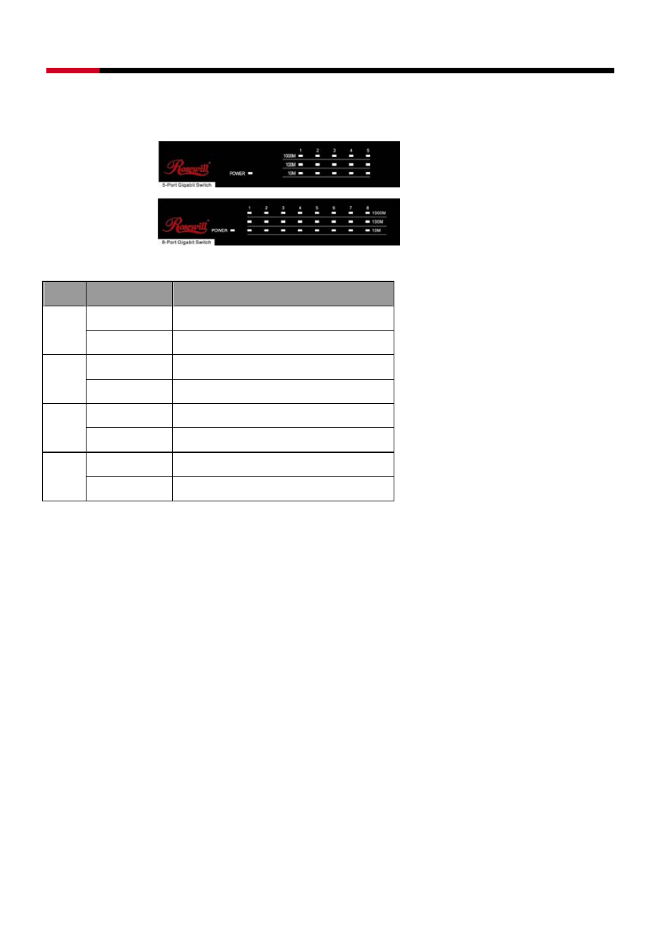
LED Definition
Please refer to the following table for LED definition
5-Port ( RC407 )
8-Port ( RC408 )
LED Status
Operation
Steady Green Power is on
Power
Off Power
is
off
Steady Green Connected as 1000Mbps
1000M
Blinking Green The port is transmitting/receiving data.
Steady Green Connected as 100Mbps
100M
Blinking Green The port is transmitting/receiving data.
Steady Green Connected as 10Mbps
10M
Blinking Green The port is transmitting/receiving data.
Stations Connection
Connect each station to the switch by twisted-pair cable. Plug one RJ-45 connector into a RJ-45 port
of the switch, and plug the other RJ-45 connector into the station’s network adapter. Power on the
switch and then system is ready.
For cable selection, refer to the following table.
Switches Connection
In making a switch interconnection, you could use any port to connect another switch with straight or
crossover cable. As all the ports support auto MDI / MDI-X function, using a straight cable to make a
switch-to-switch connection is allowed.
For cable selection, refer to the following table
: